





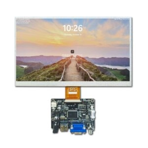
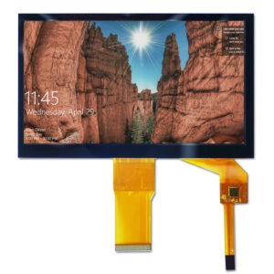


Positioning the active area correctly starts with a shared mechanical reference—not with centering the visible pixels by eye. For a custom TFT LCD assembly, define where the pixel area sits relative to the module outline, the enclosure opening, and fixed mounting datums. Then check that relationship against drawing tolerances and the actual parts.
This distinction matters because a display can match the required diagonal size and resolution yet still look misaligned once installed. The cause may be an offset between the active area and module outline, an opening positioned from different datums, or a tolerance stack that shifts the final assembly. A dimensioned drawing, agreed coordinate system, and fit check help catch these issues before design release.

What “active area placement” means
The active area is the region of the panel that produces the image. Its location is usually specified in relation to a mechanical feature, such as the module’s outer dimensions, a mounting edge, or a designated origin on a drawing. That relationship lets the enclosure designer position the display window around the image area rather than around the module as a whole.
Placement does not necessarily mean moving the pixel matrix within an existing standard panel. In a custom project, it often means coordinating the panel or module geometry with the enclosure opening, mounting features, and other constraints. Whether the display itself can be customized depends on the design and should be confirmed with the supplier.
The first task is therefore to document the desired relationship: which datum controls the location, what the horizontal and vertical offsets are, and which dimensions are fixed versus adjustable.
Distinguish active area, viewing area, and module outline
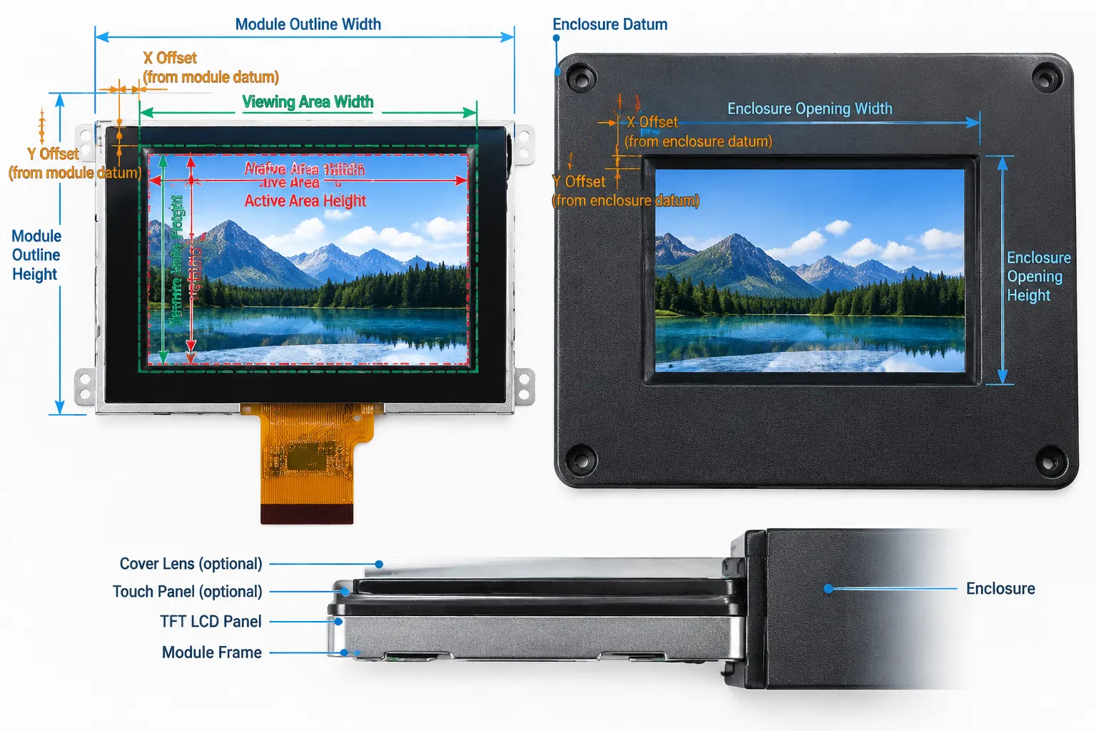
These terms describe different boundaries. The active area is the image-producing region. A datasheet may also identify a viewing area or visible area, but terminology and measurement conventions can vary, so confirm the definition on the specific drawing. The module outline describes the physical boundary of the display assembly and may include non-display regions.
The enclosure opening is a separate feature. It is the aperture through which the user sees the display, and it may be smaller than the viewing area to cover edges or accommodate the housing. If the opening is too small or shifted, it can obscure image content. If it is too large, the assembly may expose a border or internal parts that the design intended to conceal.
Do not assume the module is symmetrical around the active area. Connectors, mounting tabs, component placement, or the panel construction can make the outline asymmetric. Use the dimensioned module drawing—not the diagonal size alone—to establish the position.
Translate the display drawing into enclosure coordinates
Start by identifying a common datum scheme for the module and enclosure. For example, the mechanical drawing might locate the active area from the module’s left and top edges, while the enclosure drawing locates the window from its own mounting references. Those dimensions only describe a reliable fit when the relationship between the two coordinate systems is clear.
Record the active-area offset from the chosen module datum in both axes. Then locate the enclosure opening from the corresponding enclosure datums. If the design intentionally uses an off-center image, state the offset explicitly rather than relying on a visual mockup or an informal note such as “align to the right.”
Also specify orientation. State which edge is the top, where the connector or flexible circuit exits, and whether the drawing is viewed from the front or rear. A mirrored or rotated interpretation can preserve individual dimensions while putting the opening in the wrong place.
A practical placement workflow
- Select the display candidate.Confirm the required resolution, diagonal size, and overall module dimensions against the available specification and drawing. The product category can be used to review Miqidisplay TFT LCD display modules, but verify the exact dimensions for the selected module.
- Mark fixed enclosure references.Identify mounting holes, a bezel edge, a chassis datum, or another feature that controls assembly. Avoid defining the window only relative to a flexible or cosmetic surface if that surface does not locate the display.
- Locate the active area.Obtain the active-area width and height and its X/Y offsets from the module datum. Confirm how the drawing defines its visible-area dimensions and orientation.
- Position the window.Calculate the opening from the same reference scheme. Check that the intended image margin remains visible across the specified tolerances, while the opening still covers any areas that must stay hidden.
- Review the physical stack.Include the panel, any touch component, cover lens, adhesive, bezel, and enclosure surfaces that affect alignment. Their dimensions and assembly variation can change the apparent relationship between the image and the opening.
For a broader specification review, use a TFT LCD module datasheet checklist to compare mechanical and electrical details before releasing the enclosure design.
Allow for tolerance, not just nominal dimensions
A drawing may show a perfectly centered active area, but manufactured parts are controlled by tolerances rather than exact nominal values. The final visible alignment depends on the dimensional variation of the module, enclosure, mounting features, and opening. If adhesive or a separate front component is part of the stack, its placement may contribute as well.
List the dimensions that affect the image-to-window relationship and identify which party controls each one. Then assess the worst-case combination or another agreed tolerance method. The allowable mismatch is application-specific: a small offset may be acceptable in a concealed installation but noticeable in a narrow, symmetrical frame.
Do not add together every tolerance automatically without considering how parts are located and assembled. Instead, map the actual locating chain: which surfaces touch, which holes or edges constrain movement, and where clearance permits adjustment. This makes it easier to see whether the design needs tighter control, a larger window margin, or a different datum.
Check the full front stack
The relationship between the active area and the opening is only part of what the user sees. If the design includes a touch panel or cover lens, the front stack may add borders, printed areas, adhesive zones, or reflections. Confirm which component defines the final visible edge and whether the window is meant to reveal the active pixels, the full viewing area, or a specified margin around it.
A front-view drawing is useful for communicating the intended appearance, but it should support—not replace—the dimensioned mechanical drawing. Make sure both show the same orientation, datum, and offsets. If the assembly includes separate display and touch components, verify that their outlines and active regions are referenced consistently. Miqidisplay’s custom display solutions page is a relevant starting point for discussing a project that needs a particular component configuration.
Verify the drawing and the assembled sample
Before production release, review a dimensioned drawing that identifies the module outline, active-area dimensions and offsets, mounting references, connector orientation, and required opening. Ask the supplier to clarify any undefined term—especially “visible area” or “viewing area”—rather than interpreting it from a rendered image.
When a sample is available, inspect it in the intended mounting condition. Check alignment from the user’s normal viewing position and confirm that the opening does not cover image content or expose areas that should be concealed. If the enclosure uses adjustable features, record the final position and the adjustment range.
Keep revisions aligned. A change to the panel, module outline, mounting features, front component, or enclosure opening can affect the alignment even if the nominal diagonal remains the same. Tie the approved sample, drawing revision, and enclosure revision together so that later sourcing and assembly use the same geometry. For related considerations, see this guide to integrating a TFT LCD screen and touch panel.
What to include in a supplier inquiry
A useful technical inquiry provides enough information to check both product fit and the mechanical relationship. Include the display type, diagonal size, resolution, module outline, active-area dimensions and offsets, interface, touch requirement, brightness, viewing direction, operating temperature, and any mechanical constraints that are already fixed.
Attach the enclosure drawing or a clear front-view sketch showing the opening, mounting points, datums, and orientation. Note the expected quantity and integration environment, and identify which dimensions are provisional. These details help the supplier assess compatibility, clarify customization scope, and identify what should be checked on a sample or in the documentation. Miqidisplay can review the project inputs for a display-module fit assessment; feasibility and configuration should be confirmed for the specific design.
Conclusion
Treat active-area placement as a datum and tolerance problem, not a visual centering exercise. Confirm how the drawing defines the image region, locate it from shared mechanical references, and check the complete assembly stack against the enclosure opening. Clear drawings and a sample fit check help engineering and sourcing teams agree on the intended appearance before release.
FAQs
Is the active area the same as the viewing area?
Not necessarily. The active area is the image-producing region; a datasheet may use “viewing area” or “visible area” for a different boundary. Confirm the supplier’s drawing definitions for the exact module.
Should the active area be centered in the module outline?
Only if the design requires it and the drawing supports it. Connectors, mounting features, or other constraints may make a centered placement impractical or undesirable.
What dimensions are needed to position a TFT LCD in an enclosure?
At minimum, confirm the module outline, active-area size and offsets, opening size and location, mounting references, and orientation. Include relevant front-stack components and tolerances when applicable.
Can an existing TFT LCD module be repositioned within its outline?
Do not assume so. The active-area location is tied to the panel and module design. Confirm whether the project requires a different enclosure opening or a custom display configuration.
Request a technical fit review
If you are sourcing a TFT LCD module for a custom assembly, contact Miqidisplay for a technical fit review. Share the display type, size, outline and active-area dimensions, resolution, interface, touch requirement, brightness, viewing direction, operating temperature, mechanical constraints, quantity, drawings, and integration environment. These inputs help the team assess component compatibility, customization scope, sample requirements, and documentation needs for your project.