





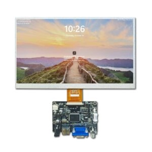
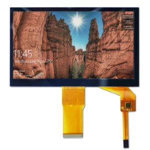

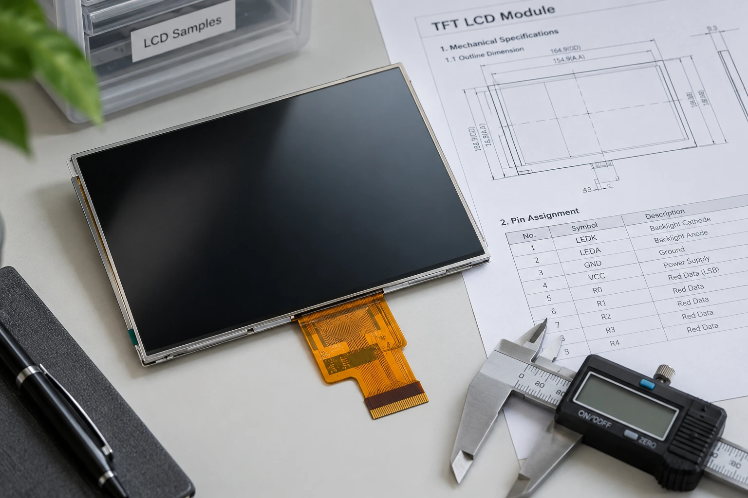
A TFT LCD module datasheet is the control document connecting enclosure design, electronics, firmware, optical requirements, environmental limits, and procurement approval. Size and resolution alone cannot determine whether a module will work with the intended equipment.
Engineering and purchasing teams should read a datasheet in a fixed sequence: confirm document identity, verify mechanical fit, check the electrical interface and pinout, validate timing and power, interpret optical values under their stated conditions, and review environmental and lifecycle information. This method helps teams screen candidate TFT LCD modules before committing resources to samples or enclosure changes.
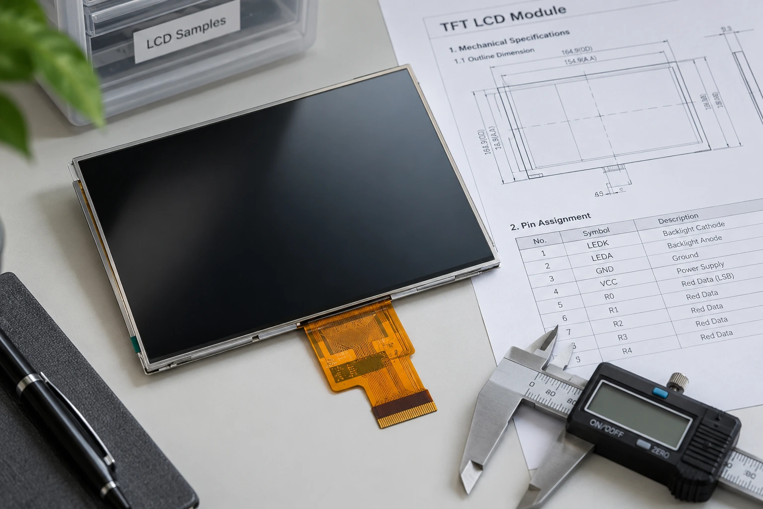
Confirm the Datasheet Identity Before Reading Specifications
Start with the manufacturer part number, document revision, issue date, and document status. A preliminary, tentative, or approval specification may change, while a released specification should still be matched to the exact part number offered.
Check whether later pages contain a revision history or notes that override the summary table. Drawings, pin tables, and timing charts should all belong to the same revision. If the quotation, sample label, and datasheet show different suffixes, procurement should pause approval until the supplier explains the difference in writing.
Read Mechanical Dimensions Before Optical Performance
The diagonal size describes the screen class, not the space required inside the equipment. Locate the module outline width, height, and thickness; active area; viewing area; mounting features; connector location; and flexible cable exit direction. Active area is the pixel-producing region, while viewing area is the opening through which the screen remains visible. These values may not be identical.
Dimensions must be read with their tolerances and datum references. The enclosure opening needs suitable margins, and nearby parts must not load the active area or flexible cable. Check component height, cable routing, connector access, and assembly clearance. If bend limits or keep-out zones are absent, they should be requested rather than assumed.
Resolution and pixel format should then be compared with the intended user interface. A notation such as 800 x 480 may be accompanied by an RGB subpixel convention, portrait orientation, or viewing direction that affects the mechanical layout.
Decode the Interface, Pinout, and Power Requirements
An interface label alone does not establish compatibility. The datasheet may also define channel or lane count, bit depth, signal mapping, clock behavior, connector model, and pin assignments. The equipment processor or controller documentation must support the same configuration. The TFT LCD interface selection guide provides useful background, but the exact module datasheet remains the approval reference.
Read every pin, including power, ground, data, clock, enable, reset, synchronization, and unused pins. A connector with the same pin count can have a different assignment. Confirm connector orientation and pin-one location on both the drawing and physical sample.
Separate logic power from backlight power. Record recommended operating values, allowable ranges, current requirements, startup order, and dimming or enable controls. Absolute maximum ratings are damage boundaries, not normal design targets. Touch functionality, when included, may have its own connector, supply, interface, and controller requirements.
Interpret Timing Tables as Operating Windows
Timing tables usually contain minimum, typical, and maximum values for pixel clock, horizontal and vertical periods, synchronization pulses, porches, setup time, and hold time. Firmware should operate inside the allowed window, not simply copy a typical value without checking the processor output.
Diagrams show signal relationships that a parameter table cannot express clearly. Check active polarity, sampling edge, data-enable behavior, reset duration, and required delays between power rails, signals, and backlight activation. A compatible interface name does not compensate for incompatible timing.
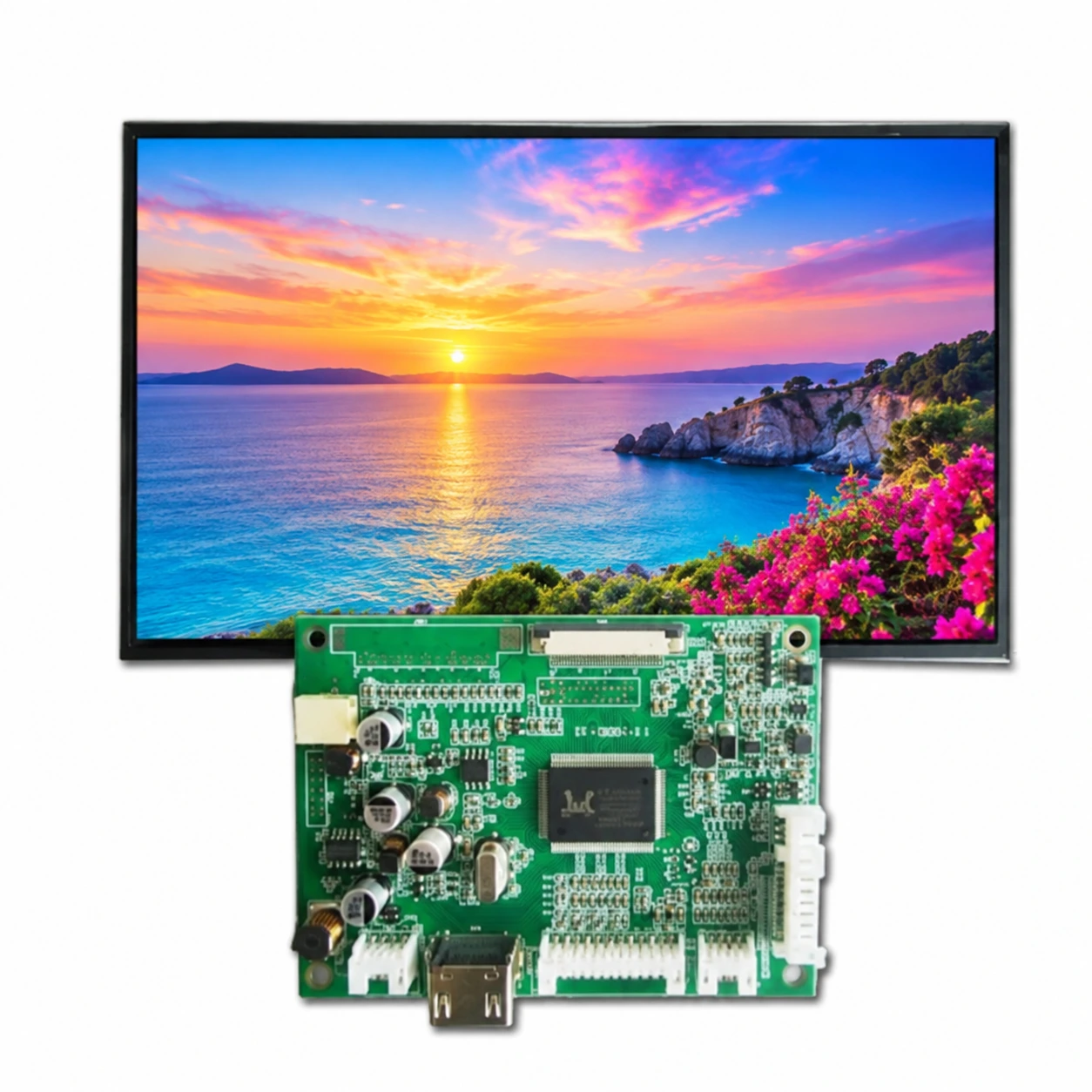
For projects involving a controller board, compare both documents line by line. This LCD panel and driver-board compatibility guide explains why resolution and connector appearance alone cannot confirm a match.
Put Optical and Environmental Values in Context
Brightness, contrast ratio, viewing angle, response time, and color characteristics depend on test methods and conditions. Determine whether a value is minimum, typical, or maximum and note the temperature, current, viewing direction, and measurement point. A typical brightness value should not automatically become an incoming-inspection minimum.
Viewing direction and viewing-angle ranges matter when operators see the screen from above, below, or from the side. Brightness should be chosen for ambient light while considering power and thermal constraints.
Operating and storage temperature ranges answer different questions. Storage limits do not authorize operation at those temperatures. Also check whether humidity, vibration, shock, surface handling, or long-duration static content is addressed. If a required condition is missing, classify it as unverified and plan an application-specific sample test.
Backlight lifetime figures must be read with their stated temperature, current, and end-of-life definition. They should not be converted into an unconditional service-life promise.
Turn the Datasheet Into a Procurement Control Record
A datasheet review should produce a controlled requirement list, not informal notes. Record each critical value, its source page, acceptance range, verification method, and responsible owner. Mark unresolved items and obtain written clarification before sample approval.
Miqidisplay presents module specifications such as size, resolution, interface, operating temperature, brightness, touch support, and display type on current product pages. Its screen-level customization options include changes to cable length, position, and pins, connector arrangements, touch additions, cover glass, and backlight parameters. Any modification should receive its own controlled drawing and specification because it can change mechanical, electrical, or optical approval criteria.
For samples, compare the label and physical construction with the controlled documents. Test the module in the intended enclosure, with the intended processor, cable routing, power sequence, content, ambient light, and temperature conditions. Procurement should also request a method for communicating specification or component changes before repeat orders.
TFT LCD Datasheet Review Checklist
| Datasheet section | Information to extract | Integration decision |
| Document control | Part number, suffix, revision, date, and status | Is this the exact offered module? |
| Mechanical drawing | Outline, thickness, active area, viewing area, cable, and connector position | Will it fit without loading sensitive areas? |
| Interface and pinout | Configuration, mapping, pin assignment, and connector orientation | Does the processor or controller match every signal? |
| Power | Logic and backlight ranges, current, sequencing, and control states | Can the design remain within recommended limits? |
| Timing | Clock, periods, pulses, porches, polarity, setup, and hold | Can firmware generate a valid operating window? |
| Optical data | Brightness, contrast, viewing direction, and test conditions | Do the values match the viewing environment? |
| Environmental data | Operating and storage limits and stated test conditions | What requires application-specific testing? |
| Touch information | Type, controller, connector, interface, and cover structure | Is touch mechanically and electrically compatible? |
Conclusion
Reading a TFT LCD module datasheet effectively means connecting every value to a design or procurement decision. Document revision, dimensions, pinout, power, timing, optical test conditions, and environmental limits should agree before a module advances to approval. Missing information is not a default value; it is an engineering question for the supplier and a test item for the project team.
FAQ
Which datasheet pages should be reviewed first?
Start with document control, the mechanical drawing, pin definition, electrical characteristics, and timing tables. Optical and environmental sections should follow once basic mechanical and electrical compatibility is established.
Does the same connector and resolution mean two modules are interchangeable?
No. Pin assignments, voltage, signal mapping, timing, cable direction, outline dimensions, and backlight requirements may still differ. Both datasheets and physical samples require comparison.
Should a typical specification become an acceptance limit?
Not automatically. Typical values describe expected behavior under stated conditions but may not be guaranteed limits. Acceptance criteria should use confirmed limits and agreed test methods.
What documents should accompany sample approval?
The package should normally include the controlled datasheet, mechanical drawing, interface and pin definition, relevant test conditions, sample identification, and written clarification of any customization or deviation.
Turn the Datasheet Into a Verified Integration Plan
Before approving a sample, engineering and procurement teams can contact Miqidisplay. Submit the exact module datasheet, mechanical drawing, processor or controller specification, target dimensions, resolution, interface, pinout, voltage, touch requirement, brightness, viewing direction, operating temperature, estimated quantity, and application environment.
Email: mary@miqidisplay.com
WhatsApp: +86 189 6801 5464; +44 07892800850