





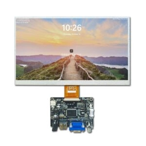
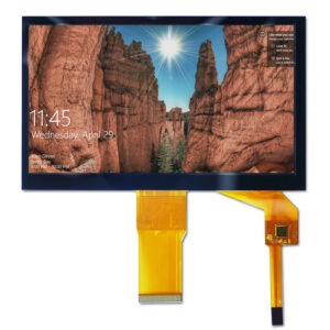

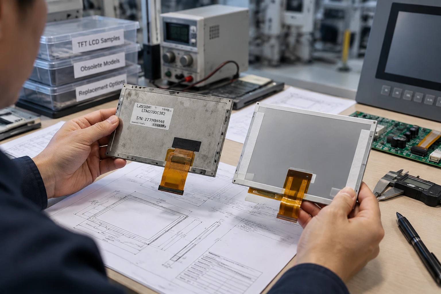
Replacing an obsolete TFT LCD panel in an OEM product is not simply a matter of matching the diagonal size. The new display module must fit the mechanical opening, accept the existing signal, meet optical requirements, and remain suitable for future production. A structured comparison helps engineering and procurement teams avoid costly redesigns and qualification delays.
1. Identify the Original Panel Precisely
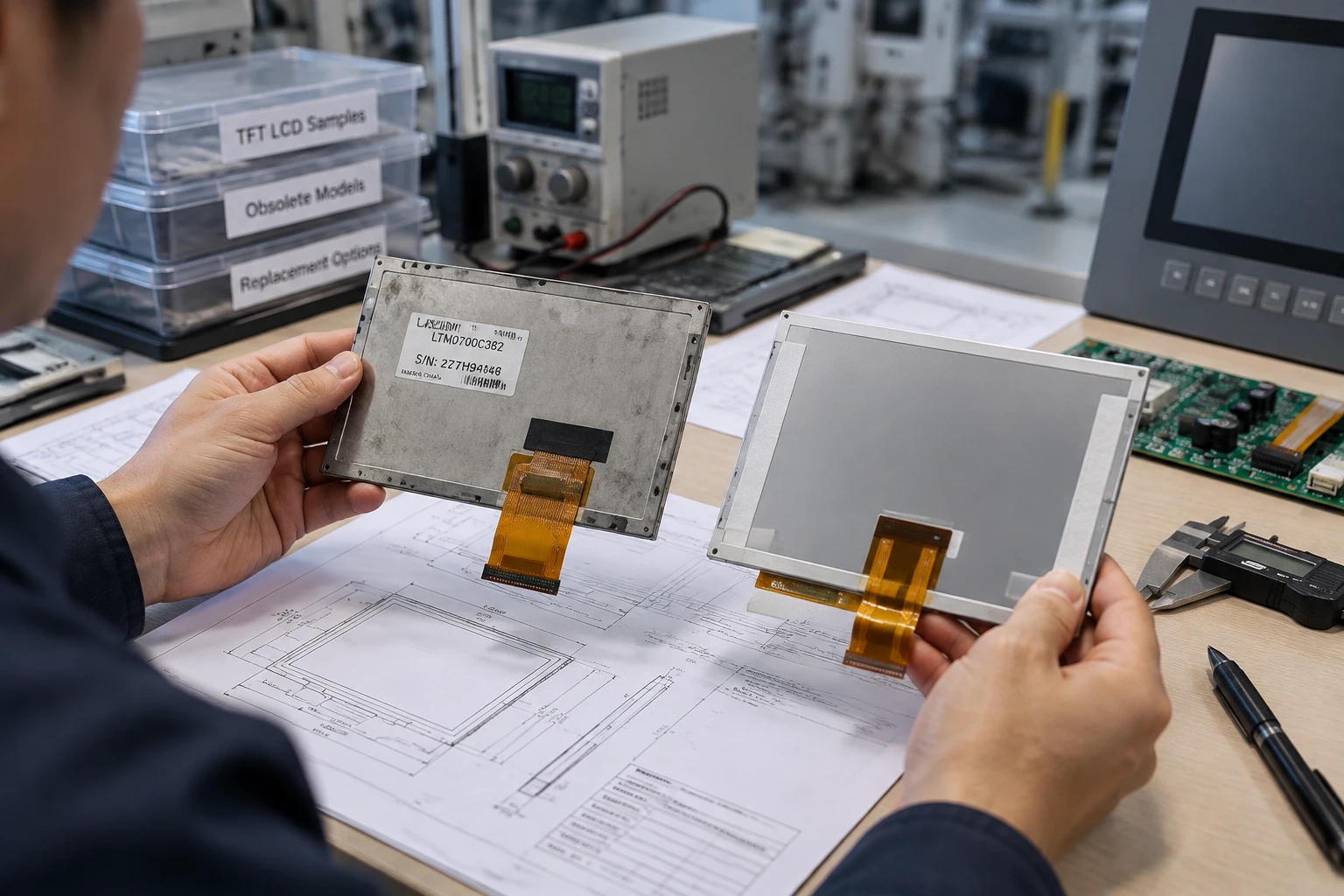
Begin with the exact part number printed on the original panel, including every suffix and revision code. Panels with similar model names may differ in connector position, timing, backlight configuration, or mounting details.
Record the following information:
- Manufacturer and complete part number
- Diagonal size and aspect ratio
- Active area and outline dimensions
- Overall thickness
- Resolution and pixel arrangement
- Connector type, position, and pin count
- Interface type
- Backlight input and control method
- Touch-panel construction, if applicable
Take clear photographs of the front, rear label, connector, cable exit, and mounting features. A technical drawing is preferable because it allows a supplier to compare tolerances rather than relying only on visual similarity.
2. Confirm the Mechanical Envelope
The diagonal measurement is only a starting point. The replacement must preserve the visible area and fit inside the existing bezel, housing, or instrument panel.
Compare:
- Active-area width and height
- Viewing-window dimensions
- Panel outline
- Border width
- Mounting holes or tabs
- Connector and FPC location
- Rear-component height
- Cable bend radius
- Clearance from nearby components
A panel with the same diagonal size may have a different aspect ratio. It may leave part of the opening uncovered or interfere with the enclosure. Thickness is also important, especially when the panel sits behind cover glass, a gasket, or a molded bezel.
If a mechanical adapter is required, treat it as a design change. It can affect rigidity, optical alignment, grounding, assembly time, and service access. Confirm the enclosure impact before approving a sample.
3. Verify Interface and Electrical Compatibility
Interface compatibility is one of the most important checks in a TFT LCD replacement project. Confirm the exact implementation of LVDS, MIPI, RGB, SPI, or another interface instead of relying on the interface name alone.
Review:
- Connector series and pin count
- Pin assignment
- Differential-pair order
- Signal voltage
- Logic voltage
- Lane configuration
- Clock or data-edge settings
- Backlight power
- Enable and reset behavior
- Touch-controller interface, if included
A candidate panel may use a connector with the same shape while assigning the pins differently. Never assume that a matching plug proves compatibility. Compare the original panel datasheet, host-board schematic, and proposed replacement pinout line by line.
For systems using a separate driver board, assess the panel and board together. Miqidisplay’s guide on LCD panel and driver-board compatibility explains why resolution, timing, interface, and power requirements must be reviewed as one system.
4. Match Resolution and Timing
Equal or higher pixel count does not automatically mean functional compatibility. The host electronics may depend on a specific pixel clock, horizontal total, vertical total, frame rate, sync polarity, or initialization sequence.
Confirm:
- Native resolution
- Aspect ratio
- Pixel clock range
- Horizontal and vertical timing
- Frame rate
- Color depth
- Data-lane count
- Sync and polarity settings
- Required initialization commands
A controller may support several resolutions, but this must be confirmed through its documentation or controlled engineering testing. Scaling can change image proportions, text sharpness, and touch-coordinate mapping. If the product uses fixed graphics, verify that the replacement preserves the intended pixel geometry.
5. Compare Optical and Environmental Requirements
The replacement must deliver the same visual function in the actual operating environment. Compare brightness, contrast, viewing direction, surface treatment, color behavior, and viewing angle.
Consider whether the display module will be used:
- Indoors or near strong ambient light
- Behind protective glass
- At a fixed operator angle
- By several users viewing from different directions
- In a dark enclosure
- Near heat-generating electronics
Brightness should be selected for the application rather than a generic “high-brightness” label. A brighter module may increase power consumption or thermal load. Anti-glare treatment, haze, and surface gloss can also change perceived contrast and reflections.
Confirm operating and storage temperatures, cold-start conditions, humidity, vibration exposure, and installation orientation. A module that performs well at room temperature may require additional validation at temperature extremes. Treat every environmental rating as a specification to verify.
6. Review Touch and Cover-Glass Integration
If the original assembly includes touch functionality, identify whether the touch layer is separate, bonded, or integrated into the display module. The replacement must match the touch active area, tail location, controller interface, cover-glass outline, and total stack height.
Check:
- Touch response through gloves or protective layers
- Cover-glass thickness
- Optical-bonding requirements
- Bezel clearance
- Surface treatment
- Flex-cable routing
- Controller and firmware dependencies
A display-only module may not be suitable when the original assembly includes touch. Conversely, adding a touch layer can affect optical performance, mechanical tolerances, and assembly processes. Define the required assembly boundary before requesting quotations.
7. Prepare a Controlled Replacement Package
A supplier can assess a replacement more accurately when the request includes complete baseline information. Send the original part number, drawings, photographs, electrical documents, application conditions, annual quantity, and target qualification schedule.
Ask for documentation covering:
- Proposed part number and revision
- Dimensional drawing
- Interface and pinout
- Optical specifications
- Backlight characteristics
- Temperature ratings
- Touch and cover-glass details
- Sample identification
- Change-notification process
- Production revision control
Do not approve a sample based only on a visual demonstration. Record the exact sample revision, test conditions, and any deviations from the original panel. This creates a reference for future production checks.
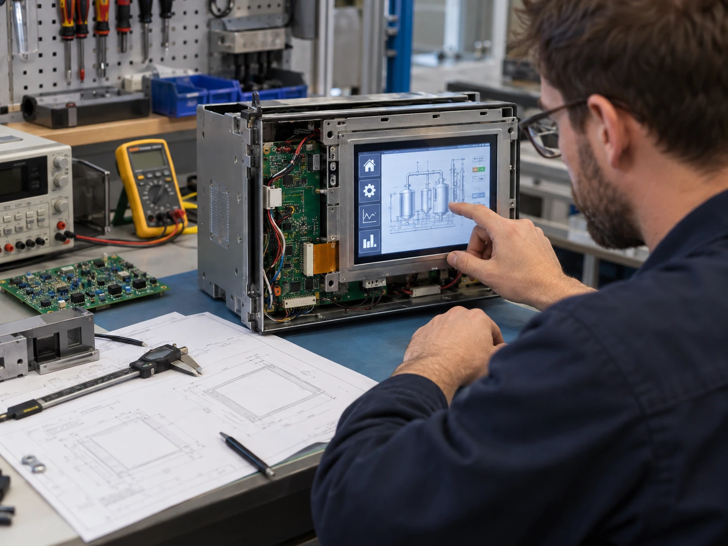
8. Validate the Module in the Actual Product
Validation should cover more than whether an image appears. Divide the process into three levels:
- Component fit:dimensions, mounting, connector access, and cable routing.
- Electrical and optical fit:signal stability, timing, brightness, image quality, and power behavior.
- Application fit:enclosure installation, touch operation, startup behavior, environmental conditions, and production assembly.
Test the replacement under representative operating conditions. Document differences in thickness, cable exit, brightness, surface treatment, or viewing direction. A small deviation may be acceptable, but it should be reviewed and approved by the responsible engineering team before the bill of materials is updated.
9. Evaluate Long-Term Supply Risk
Obsolescence replacement is also a supply-continuity decision. Ask how the proposed module will be managed after approval, including revision changes, allocation risks, quantity planning, and document updates.
Review the supplier’s approach to:
- Approved-part records
- Engineering-change notifications
- Sample-to-production consistency
- Alternate configurations
- Forecast and quantity planning
- Technical-document revisions
Miqidisplay supplies LCD screens and display modules for OEM evaluation and integration. Its industrial TFT LCD display range provides a starting point for component-level replacement projects. Buyers can also use this industrial TFT LCD supplier evaluation checklist when comparing technical and documentation requirements.
Conclusion
When replacing an obsolete TFT LCD panel, confirm more than diagonal size and resolution. Mechanical dimensions, active area, interface, pinout, timing, backlight, optical behavior, touch construction, temperature range, validation requirements, and revision control all affect the result. A structured comparison gives engineering and procurement teams a defensible basis for approving the replacement module.
FAQs
Can a panel with the same diagonal size be used directly?
No. Size alone does not confirm mechanical, electrical, optical, or timing compatibility.
Is a matching connector enough to confirm compatibility?
No. Pin assignment, voltage, signal order, timing, and backlight requirements must also be verified.
Should the original panel part number be included in an RFQ?
Yes. It provides the supplier with a reliable baseline for identifying and comparing alternatives.
When should a replacement sample be approved?
After mechanical fit, electrical and optical behavior, touch operation if applicable, and application-level requirements have been evaluated under documented conditions.
What information should an OEM provide to a supplier?
Provide the display type, size, outline dimensions, active area, resolution, interface, touch requirement, brightness, viewing direction, operating temperature, mechanical constraints, quantity, drawings, and integration environment.
Request a Technical Fit Review for Your TFT LCD Replacement
Send Miqidisplay the original panel number, display type, diagonal size, outline dimensions, active area, resolution, interface, touch requirement, brightness, viewing direction, operating temperature, mechanical constraints, quantity, drawings, and integration environment. These inputs enable a technical review of component compatibility, customization scope, sample requirements, and documentation needs. Request a Miqidisplay technical fit review for your replacement project.
Email: mary@miqidisplay.com
WhatsApp: +86 189 6801 5464; +44 07892800850