





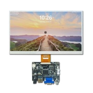
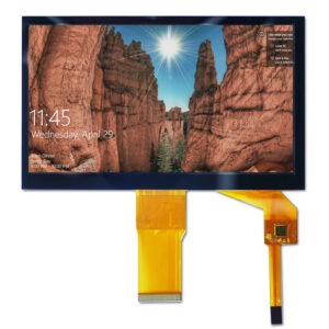

Industrial LCD panel selection usually starts from the dimension of diagonal, but diagonal dimension is not the only measurement. 10.1-inch and 10.4-inch panels will be almost the same on paper, yet there can be considerable differences between the two in terms of shape, visual dimensions, mechanical construction, electrical design, and integration needs. Using them interchangeably can lead to issues with the enclosure, new cabling, signal compatibility, programming changes, and unanticipated expenses for tooling.
Diagonal Size Does Not Define Panel Geometry
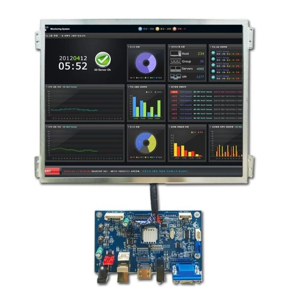
Diagonal measurement refers to the measurement of the distance from one corner to another on the screen area. It doesn’t indicate the width of the screen, height of the screen, border measurements, thickness or any mounting measurements. The aspect ratio dictates how the diagonal is split.
A common 10.1-inch industrial TFT LCD uses a 16:10 aspect ratio, an active area of about 216.96 × 135.6 mm, and a native resolution of 1280 × 800. A common 10.4-inch configuration uses a 4:3 aspect ratio, an active area near 211.2 × 158.4 mm, and may use 1024 × 768 or 800 × 600 resolution. The 10.1-inch option can therefore be wider, while the 10.4-inch option can be much taller, despite only a 0.3-inch diagonal difference.
Aspect Ratio Changes the Interface Layout
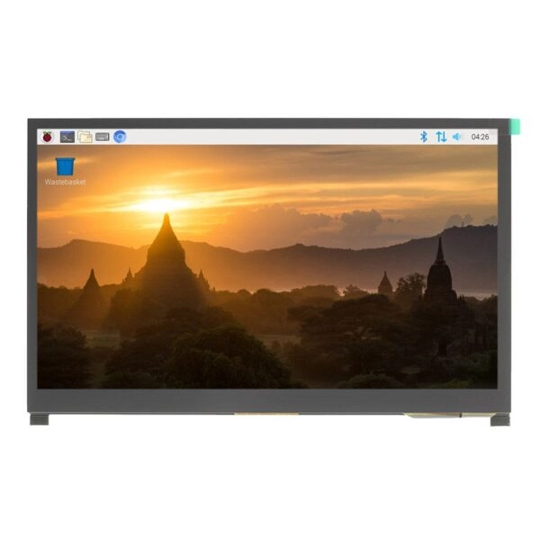
The wider 16:10 format supports horizontal dashboards, process trends, multi-column status fields, and side-by-side machine data. The taller 4:3 format may suit legacy layouts, vertically stacked parameters, inspection images, or established equipment designs.
Changing aspect ratio can distort or crop content and trigger renewed software validation because graphical elements no longer occupy the same pixel coordinates.
Active Area Determines the Visible Window
Active area is the addressable region that presents information. It is not the outer glass, metal frame, or enclosure opening. In the examples above, the 10.4-inch active area is narrower than the 10.1-inch area but about 22.8 mm taller.
That difference affects the viewing window, gasket position, bonding dimensions, and front-housing alignment. Specifications should include active width and height.
Mechanical Compatibility Requires Drawing Review
Mechanical drawings are decisive for any drop-in replacement assessment. Even panels with identical diagonal size and active area can have different outer dimensions. Published 10.1-inch examples show outlines of approximately 247.0 × 166.0 × 10.7 mm and 230.56 × 155.01 × 6.4 mm. Nominal screen size therefore cannot establish mechanical interchangeability, even within the same diagonal category.
Outline Dimensions, Thickness, and Tolerance
Outline width and height determine whether the panel fits inside the chassis. Thickness affects rear clearance, bracket depth, cable bend radius, thermal spacing, and pressure on nearby circuit boards. A few millimeters can force changes to sheet metal, molded parts, internal supports, or front bezels.
Production fit should be verified through tolerance-stack analysis.
Mounting Points and Structural Support
Mounting tabs, screw holes, frame edges, brackets, and adhesive zones are model-specific. Their positions determine load distribution and resistance to vibration or mechanical shock. A panel that fits the cavity but lacks matching mounting points is not a drop-in replacement.
Approved drawings should define mounting surfaces, keep-out zones, fastener locations, and pressure limits.
Enclosure Cutout and Bezel Opening
The enclosure cutout must match the visible region while covering inactive borders. A cutout designed for a wide 10.1-inch panel will generally not align with the taller 10.4-inch geometry. Reusing the opening can expose borders, hide usable pixels, interfere with seals, or create an unacceptable visual gap.
Front glass, printed borders, gaskets, and bonding fixtures may require new tooling.
Electrical Compatibility Extends Beyond Interface Names
An interface label such as LVDS does not confirm plug compatibility. Integration depends on connector family, pin count, pitch, orientation, channel configuration, bit mapping, timing, grounding, and power sequence.
Published examples illustrate the risk: a 10.1-inch module may use a 40-pin connector, while a 10.4-inch module may use a 20-pin connector. Both can use LVDS signaling, yet their physical connection and pin assignment remain different.
Connector Location and Cable Routing
Connector placement affects cable length, folding direction, bend radius, shielding, and assembly access. A connector moved to another edge can conflict with structural parts or require a new flexible cable. Orientation determines whether the cable exits into available space or into an obstruction.
Voltage Rails and Power Sequence
Logic voltage, illumination voltage, current demand, enable signals, and dimming control must be checked separately. A panel may use 3.3 V logic while requiring a different illumination supply. Maximum ratings are not operating targets, and an incorrect rail can permanently damage the module.
Qualification should also verify power timing, inrush current, ripple limits, and control polarity. Published specifications show 3.3 V logic operation alongside separate supply requirements and model-specific sequencing.
Resolution Affects Electronics and Software
Resolution determines the pixel matrix expected by the graphics source. Moving from 1280 × 800 to 1024 × 768 or 800 × 600 changes pixel clock, timing, aspect ratio, pixel density, and graphical asset placement. The controller may need new timing parameters, while software may require a revised layout.
Scaling can reduce clarity, distort shapes, and shift warning graphics, making native-resolution operation preferable for critical industrial information.
Industrial Replacement Qualification Process
A controlled replacement process should begin with the original panel specification, mechanical drawing, cable drawing, enclosure drawing, and electrical interface definition. Candidate panels should be checked for active area, aspect ratio, outline dimensions, thickness, mounting geometry, connector location, pinout, signal format, voltage rails, timing, operating temperature, luminance, viewing direction, and lifecycle status.
Sample validation should cover fit, cable routing, image mapping, power sequencing, thermal behavior, vibration exposure, and sustained operation under representative conditions. Approval should be based on documented test evidence and revision-controlled drawings.
The sourcing rule is clear: 10.1-inch and 10.4-inch LCD panels occupy different mechanical and electrical design spaces. Similar diagonal measurements can support initial filtering, but not a substitution decision.
FAQ
Can a 10.4-inch LCD panel replace a 10.1-inch panel?
Not without full qualification. Aspect ratio, active area, outline size, mounting points, enclosure opening, connector, interface mapping, voltage, and timing must match or be redesigned.
Are all 10.1-inch LCD panels mechanically identical?
No. Panels with the same diagonal and active area can still have different outer dimensions, thicknesses, frames, connectors, and mounting structures.
Is matching resolution enough for compatibility?
No. Resolution addresses only the pixel matrix. Mechanical fit, connector pinout, signal timing, voltage rails, cable routing, and environmental requirements remain independent.
Can two panels with LVDS interfaces use the same cable?
Only when connector type, pin count, pin assignment, lane mapping, bit depth, control pins, grounding, and orientation are confirmed. The shared interface name alone is insufficient.
Work With an Industrial LCD Panel Manufacturer and Supplier
Miqidisplay is an advanced display technology and solutions supplier providing LCD, TFT, IPS, VFD panels, and specialized accessories for industrial projects. As a display manufacturer, Miqidisplay supports specification review and custom requirements involving cable length and position, connector configuration, interface adaptation, mounting features, and panel integration.
Procurement teams can submit the existing panel model, drawings, electrical requirements, target quantity, and application conditions through the Contact Us page to request a compatibility assessment and project quotation.