





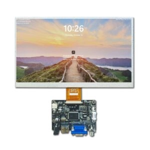
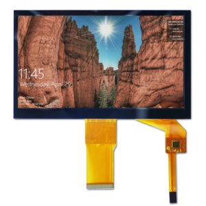

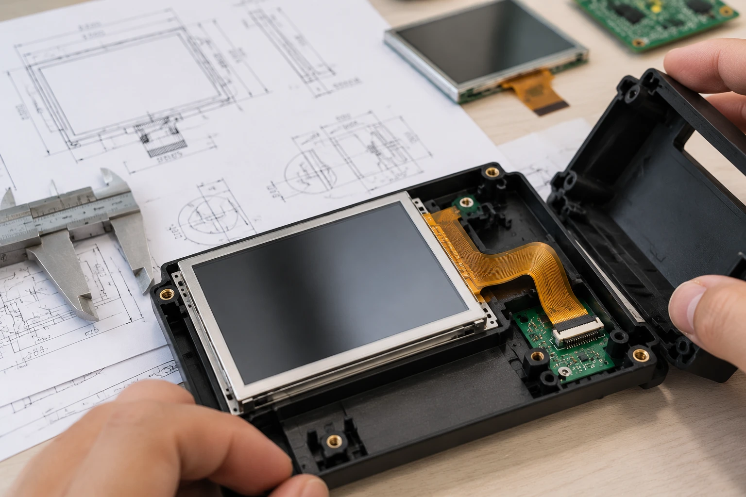
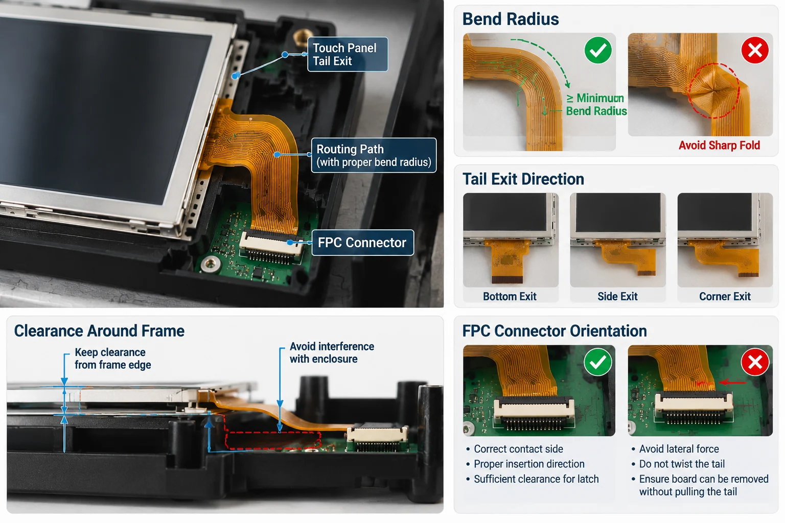
Routing a resistive touch tail inside a small LCD assembly is primarily a mechanical and electrical integration task. The tail must exit the touch panel without exceeding its allowable bend radius, interfering with the LCD frame, stressing the connector, or creating assembly variation. A reliable design begins with the tail geometry and connector location—not with the enclosure opening.
For buyers sourcing a compact resistive touch panel and LCD module, the goal is to define a controlled path from the touch sensor to the connector while preserving clearance, repeatability, and service access.
Understand the Tail Before Designing the Route
A resistive touch panel typically uses a flexible printed tail to connect the touch electrodes to a controller or host board. Depending on the panel construction, the tail may contain four or five conductive paths and may exit from a selected edge or corner.
Before creating the mechanical drawing, confirm:
- Tail exit side and exact exit position
- Tail length from the sensor edge to the contact area
- Contact pitch and exposed-contact orientation
- Stiffener dimensions at the connector end
- Allowed bending direction
- Minimum bend radius for the flexible section
- Whether the tail can be folded or must remain flat
- Connector type and mating direction
Do not assume that two resistive touch panels with the same diagonal size have interchangeable tails. The active area, outline, tail position, stiffener, and connector orientation can all differ. A product category such as Miqidisplay’s resistive touch screen range can help identify suitable module formats, but the final route should be based on the selected drawing and sample.
Choose the Exit Direction First
In a small assembly, the shortest tail route is not always the safest. A direct path may place the tail against a sharp frame edge or force an unsuitable fold near the sensor seal.
Evaluate each possible exit direction against the enclosure:
- Identify the side with the least obstruction from the LCD frame, backlight, driver board, and mounting hardware.
- Check whether the connector can be installed without twisting the tail.
- Reserve a smooth transition zone immediately after the tail exits the panel.
- Keep the route away from screw bosses, clips, springs, and sliding parts.
- Confirm that the route does not cross an area compressed by the bezel.
A side exit may be appropriate when the controller is located beside the display. A rear fold may be more practical when the board is behind the LCD, but only if the fold radius and vertical clearance are controlled. The correct choice depends on the complete stack-up, not only on the position of the connector.
Protect the Bend Radius
The most common routing mistake is creating a tight crease where the tail changes direction. A flexible tail can tolerate controlled bending, but a sharp fold can damage conductive traces or create intermittent electrical behavior over time.
Use the supplier’s bend-radius requirement as the controlling value. If a specific value is not provided, request clarification before finalizing the mechanical design. The acceptable radius may vary with copper construction, stiffener length, tail thickness, bend direction, and the number of assembly cycles.
A safe routing concept normally includes:
- A straight section at the tail exit
- A gradual curve rather than a sharp corner
- No crease across the contact area
- No bending directly over the stiffener transition
- No repeated flexing during installation
- No compression between rigid parts
The tail should be supported by the surrounding structure without being clamped so tightly that the flexible section becomes a load-bearing part.
Match the FPC Connector Orientation
A ZIF or FPC connector must align with the exposed contacts on the tail. The connector’s contact side, latch position, insertion direction, and board location all influence the routing path.
Before releasing the PCB layout, verify:
- Contacts face the correct direction
- Tail insertion depth is adequate
- The latch can be opened and closed after installation
- The connector body does not collide with the LCD frame
- The tail enters the connector without lateral force
- The board can be removed without pulling the tail
If the connector is rotated 180 degrees, the tail may need an additional fold. That fold can consume the available clearance and place stress near the sensor edge. It is usually better to correct the connector orientation early than to compensate with a complex tail path.
For compact applications, a small 2.8-inch SPI TFT LCD with resistive touch can be evaluated as a complete display-module reference, but its tail and connector arrangement should not be assumed to match another size or resolution.
Design Clearance Around the Frame
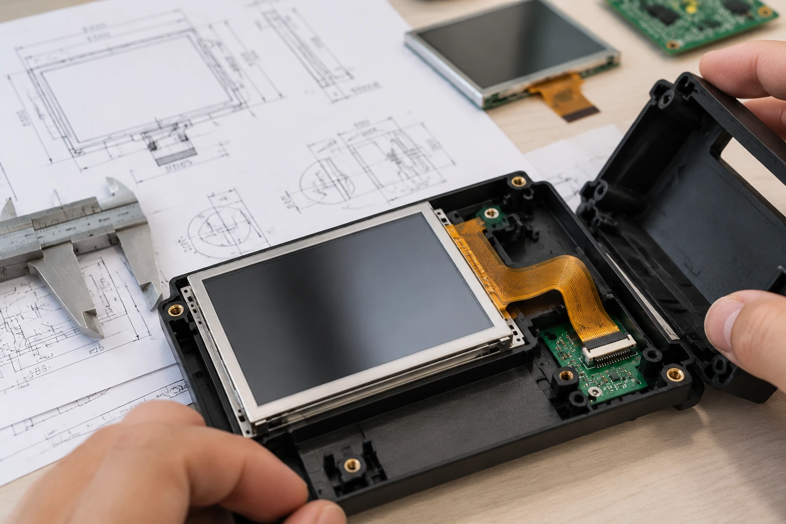
The tail route must be checked against the complete mechanical cross-section. Small LCD assemblies often have little unused space between the panel, bezel, rear cover, and circuit board.
Create a clearance review that includes:
- LCD glass and polarizer edges
- Touch-panel perimeter
- Backlight frame
- Metal or plastic bezel
- Adhesive layers
- PCB thickness
- Connector height
- Fasteners and locating features
- Cable exit and enclosure opening
Avoid routing the tail across a sharp stamped edge or an unfinished molded feature. If the route passes near a frame edge, specify a radius, chamfer, protective film, or dedicated channel. A channel should guide the tail without creating a narrow pinch point.
The tail should also remain clear of areas where the assembly experiences compression. A bezel that presses on the tail may create a permanent crease, alter the touch-panel stack, or prevent the enclosure from closing consistently.
Add Strain Relief Without Over-Constraining the Tail
Strain relief is intended to prevent connector loads from being transferred to the sensor tail. It should stabilize the route while allowing the flexible section to follow its designed curve.
Possible approaches include:
- A molded guide in the rear housing
- A low-force adhesive support
- A soft retaining clip
- A dedicated pocket beside the display
- A controlled tape location defined in the assembly drawing
Do not place adhesive over the exposed contacts or across a region that must flex. Also avoid relying on a single adhesive strip to hold the tail in a position that is naturally unstable. The support method should be evaluated for the assembly’s temperature range, materials, and expected handling conditions.
A good design makes the correct route obvious to the assembler. If the tail can be installed in several different positions, add a visual datum, guide feature, or drawing note.
Validate the Route Electrically and Mechanically
A routing design is not complete when the tail fits in the first sample. It should be checked after repeated assembly and under the expected operating conditions.
Use a validation sequence that includes:
- Inspect the tail and connector before assembly.
- Confirm that the tail enters the connector squarely.
- Check latch engagement and insertion depth.
- Measure clearance after the bezel and rear cover are installed.
- Operate the touch panel across the active area.
- Move or flex the housing only within the intended mechanical range.
- Repeat the installation process with multiple samples.
- Record any change in touch response, display behavior, or connector retention.
If an electrical issue appears only after the enclosure is closed, look first for compression, twisting, or an unintended bend. If the route is correct but the interface remains unstable, review the connector specification, controller compatibility, grounding approach, and tail contact orientation.
The validation record should identify the approved tail drawing, connector part, fold direction, support points, and assembly sequence. This prevents a later production change from silently creating a new routing condition.
What to Include in an RFQ
A supplier cannot reliably assess a small LCD assembly route from diagonal size alone. Include the following information in the RFQ:
- LCD type and diagonal size
- Active area and outline dimensions
- Resolution and viewing direction
- Resistive touch requirement and wire configuration
- Tail exit location
- Tail length and connector preference
- Available bend envelope
- Frame, bezel, and housing drawings
- Interface and controller information
- Operating temperature
- Quantity and sample requirements
- Assembly photographs or three-dimensional data when available
If the tail route is constrained by a narrow enclosure, provide a section view showing the available height and the intended connector location. This allows the supplier to identify whether the requested tail geometry is practical or whether the exit direction should change.
For projects requiring a tailored module, Miqidisplay’s custom display solutions can be used as the starting point for a technical discussion. The relevant review may include panel dimensions, touch construction, tail arrangement, connector compatibility, drawings, and sample validation requirements.
Conclusion
Routing a resistive touch tail in a small LCD assembly requires coordinated control of geometry, bend radius, connector orientation, frame clearance, strain relief, and validation. The most robust route is the one that can be repeated by different assemblers without forcing the tail into a sharp fold or allowing the connector to carry mechanical load.
Treat the tail as part of the module interface from the beginning. Confirm the drawing, reserve the bend envelope, check the closed assembly, and validate the route with representative samples before production approval.
FAQs
Can a resistive touch tail be folded behind a small LCD?
It may be possible, but only when the fold direction, radius, stiffener transition, and available clearance match the supplier’s requirements. A fold should be confirmed against the final drawing and sample.
Should the connector be placed on the same side as the tail exit?
Usually, this simplifies routing and reduces the number of bends. However, the best position depends on the board layout, enclosure space, latch access, and the complete mechanical stack-up.
What causes intermittent touch behavior after assembly?
Common possibilities include tail compression, excessive bending, incomplete connector insertion, incorrect contact orientation, or mechanical stress transferred from the enclosure. These conditions should be checked systematically.
Is a longer tail always better for assembly?
No. Extra length can create loops, pinch points, or unwanted movement. The tail should be long enough to reach the connector with the required bend radius and assembly tolerance, but not so long that it becomes difficult to control.
What should be approved before production?
Approve the LCD and touch-panel drawing, tail exit direction, connector orientation, bend path, support method, enclosure clearance, assembly sequence, and electrical validation results.
To request a Miqidisplay technical fit review, send the display type, diagonal size, outline dimensions, active area, resolution, interface, touch requirement, brightness, viewing direction, operating temperature, mechanical constraints, quantity, drawings, and integration environment. These inputs allow the technical team to assess component compatibility, routing constraints, customization scope, sample requirements, and documentation needs before a quotation assessment.
Email: mary@miqidisplay.com
WhatsApp: +86 189 6801 5464