






TFT LCD flicker in a long-viewing application is usually controlled through coordinated choices in the display module, backlight drive, power rail, image timing, and validation process. Changing only the refresh setting may not solve the problem because flicker can originate from luminance modulation, unstable power, timing mismatch, or repeated full-screen redraws.
For OEM equipment, the practical objective is not simply to make a display appear stable in one test condition. The display should remain visually consistent across brightness levels, operating temperatures, interfaces, content patterns, and production batches.
What TFT LCD Flicker Means
Flicker is a time-dependent change in perceived luminance. In a TFT LCD system, it may come from the backlight control signal, panel timing, power fluctuation, or software rendering behavior.
Several symptoms can look similar:
- Backlight modulation:The backlight current is repeatedly switched or adjusted. Low-frequency modulation can become visible or uncomfortable during extended viewing.
- Frame or image instability:Incorrect pixel timing, refresh configuration, or synchronization can create flashing, tearing, or periodic brightness changes.
- Panel drive imbalance:VCOM or other panel drive parameters may be incorrectly configured for the selected module.
- Power-related variation:Ripple, voltage drop, or insufficient decoupling can change the brightness or stability of the display.
- Redraw artifacts:A controller that clears and redraws the entire image repeatedly may create visible flashes even when the panel itself is operating correctly.
The first design task is therefore to identify whether the change is optical, electrical, timing-related, or software-generated. A camera can help reveal periodic changes, but it should not be the only acceptance method.
Start with a Flicker-Conscious TFT LCD Module
The TFT LCD module specification should state how brightness is controlled and what operating conditions were used for validation. When comparing candidate panels, ask for:
- The backlight control method, such as PWM, analog control, or a supported constant-current mode.
- The usable dimming range and the recommended minimum brightness setting.
- The PWM frequency or modulation behavior at each brightness level, if PWM is used.
- The panel refresh range, pixel clock requirements, and supported timing parameters.
- The recommended VCOM and power-sequencing conditions.
- The interface type and driver-board requirements.
- The operating-temperature range and any brightness variation expected across that range.
A higher modulation frequency may reduce visible flicker, but it does not automatically make every system comfortable. The result depends on duty cycle, optical output, camera exposure, viewing distance, and the sensitivity of the application. Where the module supports it, a stable analog or constant-current dimming method may be preferable for long-viewing use, subject to the panel specification.
For sourcing, buyers can review Miqidisplay’s AUO LCD Screen category as one example of a component-level LCD selection path. The relevant choice still depends on size, resolution, interface, brightness, temperature, and mechanical fit.
Stabilize the Power and Backlight Path
A display can appear to flicker when the actual problem is a fluctuating supply. The backlight and panel logic should be evaluated separately because they may have different voltage and current requirements.
Use a regulated rail with adequate transient response, local decoupling, and short return paths. Check the supply during startup, brightness changes, processor load changes, and communication activity. Cable resistance and connector contacts can produce voltage variation that is not visible in a no-load measurement.
The backlight control line also needs attention. A long or noisy PWM trace can introduce ringing or unintended modulation. Confirm the logic-level compatibility between the host controller and the display driver. If a driver board is used, verify its input range, enable sequence, dimming behavior, and grounding arrangement.
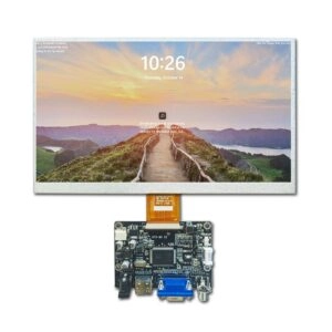
Miqidisplay’s Display with Driver Board category is relevant when an application needs a display component and controller combination that can be evaluated together. The exact electrical interface and compatibility should be confirmed against the selected product documentation.
Match Image Timing and Rendering Behavior
A stable electrical design can still produce visible flashing when the host timing is incorrect. Configure the pixel clock, horizontal and vertical timings, refresh rate, synchronization polarity, and interface mode according to the panel datasheet.
Do not assume that a higher refresh setting is automatically better. The controller, interface bandwidth, frame buffer, and panel timing must operate within a compatible range. An unstable link can create intermittent artifacts that are mistaken for backlight flicker.
Software rendering also matters. Avoid clearing the entire frame before every update when only a small region has changed. Dirty-region updates, double buffering, and synchronized frame swaps can reduce redraw artifacts. For moving content, test transitions, scrolling text, gauges, and rapidly changing data rather than using only a static image.
For engineering teams reviewing these parameters, Miqidisplay’s TFT LCD module datasheet guide provides a useful reference point for organizing interface, timing, and mechanical data during integration.
Design for Long-Viewing Comfort
Long-viewing applications require more than a flicker-free appearance at maximum brightness. Excessive luminance, reflections, poor contrast, and abrupt brightness changes can all reduce viewing comfort.
Set a practical operating range instead of allowing the software to move continuously between extreme brightness levels. Use gradual transitions when the application changes brightness. Evaluate the display under the actual ambient-light conditions, viewing direction, protective cover, and enclosure geometry.
Surface treatment should also be considered. An anti-glare or optical solution may reduce reflections, but it can affect contrast, color appearance, and transmission. These trade-offs should be assessed with production-like cover materials rather than a bare panel.
The viewing test should include the intended distance and angle. A module that appears stable directly in front of the panel may behave differently when viewed off-axis or through a protective window.
Validate Flicker Before Production Release
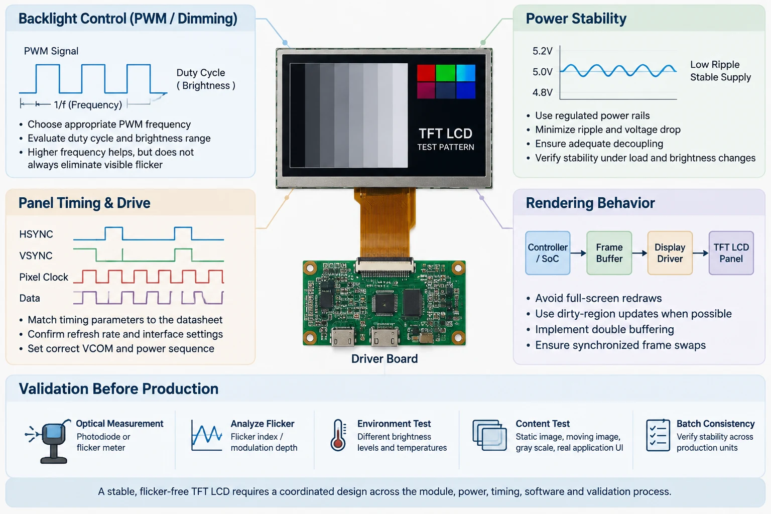
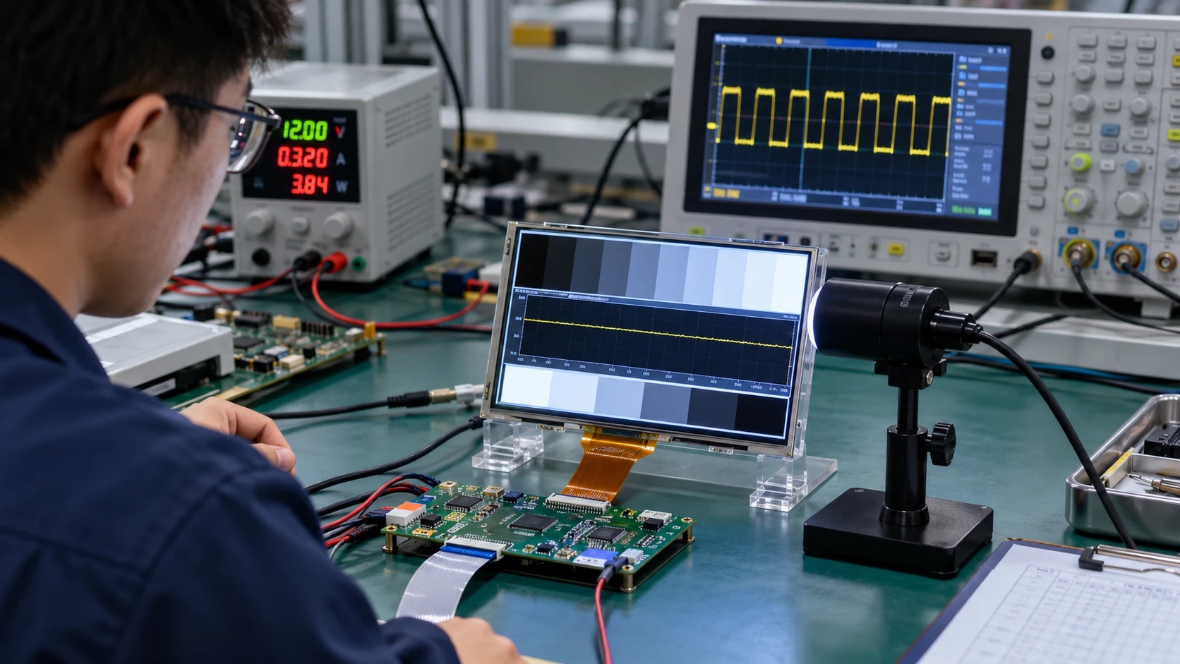
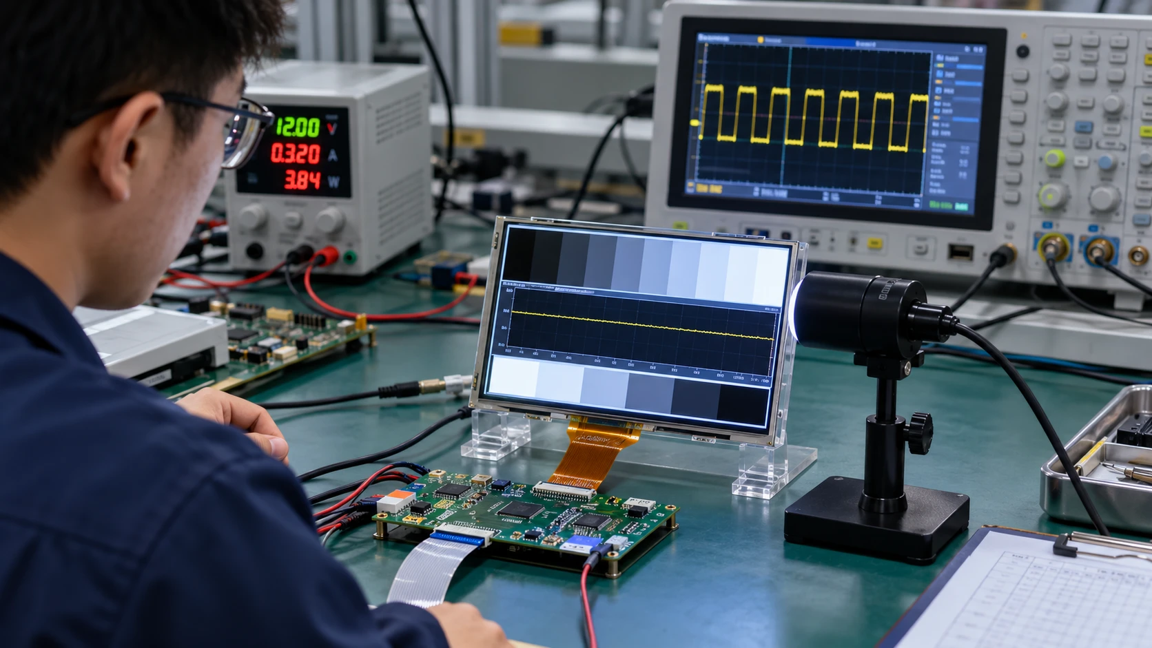
A repeatable validation protocol is more useful than a single visual inspection. A practical test sequence includes:
- Measure luminance variation with a photodiode, flicker meter, or suitable optical sensor.
- Test several brightness levels, including the lowest intended setting.
- Run static images, scrolling content, fast transitions, and partial updates.
- Check startup, wake-up, sleep, and brightness-transition behavior.
- Repeat tests at relevant low, room, and high temperatures.
- Measure the supply rail and backlight control signal at the same time.
- Test the final cable, connector, enclosure, cover, and grounding arrangement.
- Compare samples from more than one production lot when available.
Record the test equipment, sensor position, sampling conditions, display settings, firmware version, and acceptance limits. This creates a common reference for the display supplier, electronics team, and quality team.
If flicker appears only at one brightness level or during a particular image transition, preserve the exact conditions. Reproducing the same state is essential for determining whether the next action involves the module, driver configuration, power design, or rendering pipeline.
Procurement Questions for a TFT LCD Project
Before approving a module, ask the supplier to clarify:
- Which dimming methods are supported?
- Is the brightness-control behavior documented across the full operating range?
- Are panel timing and VCOM parameters available?
- What driver-board and interface combinations are supported?
- What information is needed for flicker or visual-stability validation?
- Can the supplier review the complete electrical and mechanical integration conditions?
- How will approved display revisions and production samples be identified?
These questions help prevent a late-stage discovery that the selected panel cannot meet the intended viewing conditions without changing the power design or software architecture.
How Miqidisplay Can Support Component Fit
Miqidisplay presents LCD screens and display components for OEM integration, including original LCD categories and display assemblies with driver boards. Its company information can help procurement and engineering teams understand the component-sourcing context before requesting a technical review.
Send the display type, diagonal size, outline dimensions, active area, resolution, interface, touch requirement, brightness, viewing direction, operating temperature, mechanical constraints, quantity, drawings, and integration environment. These inputs allow Miqidisplay to assess component compatibility, possible customization scope, sample requirements, and documentation needs.
Conclusion
Controlling TFT LCD flicker in long-viewing applications requires a system-level approach. Select a module with a suitable brightness-control method, stabilize the power and backlight path, match panel timing, minimize redraw artifacts, and validate the complete assembly under realistic conditions. A documented test method gives engineering and procurement teams a reliable basis for approving the display component.
FAQs
Can a higher refresh rate eliminate TFT LCD flicker?
Not necessarily. Flicker may come from backlight modulation, power instability, VCOM configuration, or redraw behavior. Refresh rate is only one part of the evaluation.
Is PWM always unsuitable for long-viewing applications?
No. The result depends on modulation frequency, duty cycle, brightness range, optical output, and the application. The complete module should be measured under intended conditions.
Should flicker be tested only at maximum brightness?
No. Low and intermediate brightness levels often create different modulation behavior. Test every brightness range used by the product.
Can a driver board change flicker performance?
Yes. A driver board can affect timing, power regulation, dimming control, and signal integrity. The panel and driver combination should be validated together.
What should be included in a supplier inquiry?
Provide the panel size, resolution, interface, brightness, dimming method, operating temperature, mechanical constraints, quantity, drawings, and integration environment.
To begin a B2B fit assessment, contact the Miqidisplay technical team with your display specification and test conditions. This enables a focused review of module compatibility, driver-board options, customization requirements, and sample-validation needs before a quotation assessment.
Email: mary@miqidisplay.com
WhatsApp: +86 189 6801 5464; +44 07892800850