





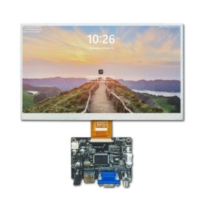
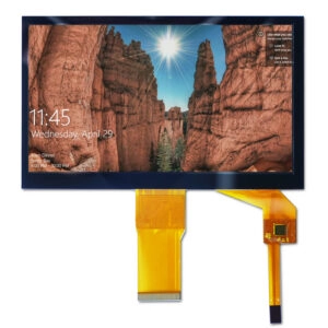


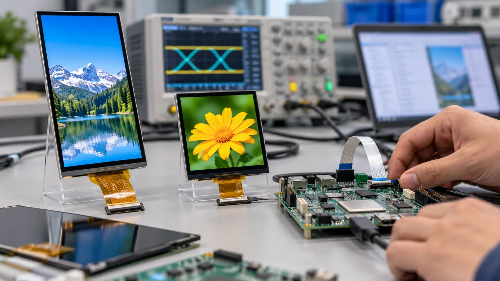
Selecting an LCD controller for a MIPI DSI panel requires more than matching the connector. The controller must provide enough data lanes, lane speed, pixel-format support, timing flexibility, and electrical compatibility for the selected LCD module.
MIPI DSI lane count determines how the display payload is distributed across the physical interface. Bandwidth determines whether the controller can deliver every pixel at the required resolution and refresh rate. A mismatch can cause unstable images, dropped frames, startup failures, or a design that works only under limited conditions.
For engineers sourcing an LCD module, the correct process is to calculate the required data rate first, then compare it with the controller and panel specifications.
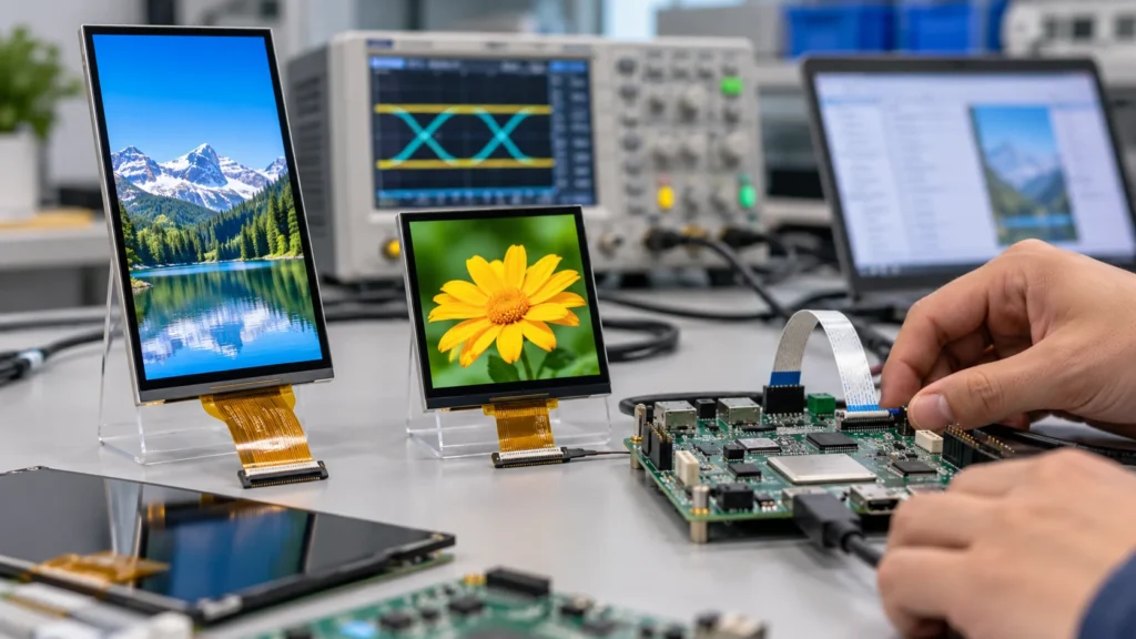
What MIPI DSI Lane Count Means
A typical MIPI DSI D-PHY connection includes one differential clock lane and one or more differential data lanes. Many display implementations use one, two, or four data lanes. The clock lane is not counted as a pixel-data lane.
More data lanes allow the same display payload to be distributed across more physical channels. For example, a four-lane design can carry approximately twice the aggregate data of a two-lane design when the lane rate is unchanged. However, additional lanes also affect PCB routing, connector assignments, pin availability, software configuration, and controller cost.
Lane count should therefore be selected from the complete system requirement rather than treated as a universal performance ranking.
A lower-resolution panel with a moderate refresh rate may work with one or two data lanes. A larger or vertically oriented panel with high pixel density may require four lanes. The panel datasheet, controller datasheet, and host processor documentation must agree on the supported lane count. A controller that supports four lanes does not automatically make a one-lane panel compatible with every software configuration.
Engineers should also confirm whether the panel expects video mode, command mode, or a particular initialization sequence. These settings affect how pixel data is transferred and how display memory is used.
How to Calculate MIPI DSI Bandwidth
The first calculation estimates the active pixel payload:
Active payload = horizontal resolution × vertical resolution × refresh rate × bits per pixel
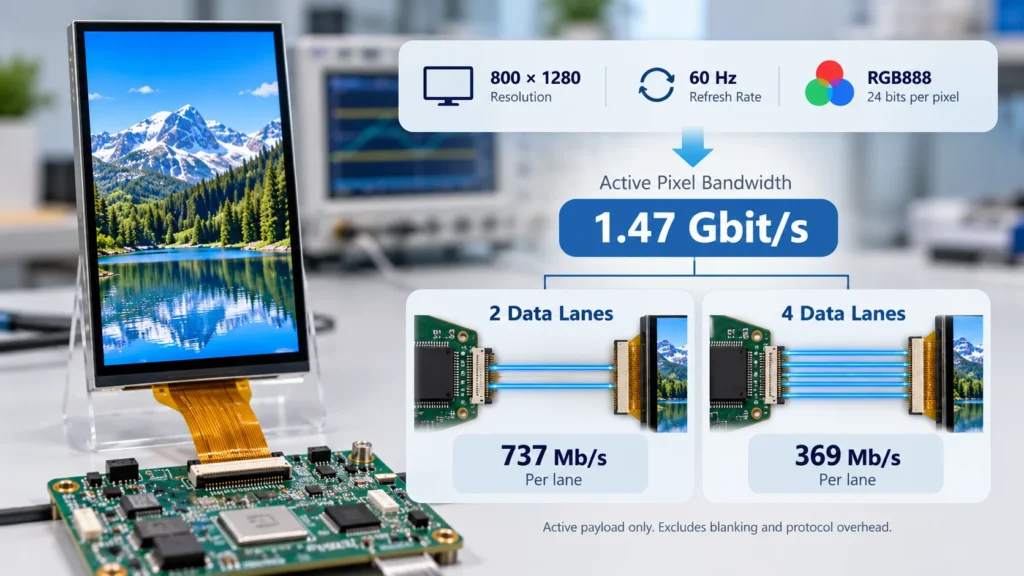
For an 800 × 1280 panel operating at 60 Hz with RGB888 color:
800 × 1280 × 60 × 24 = 1.47456 Gbit/s
This is only the active image payload. It does not yet include horizontal and vertical blanking, packet headers, escape-mode transactions, synchronization requirements, error-checking fields, or other protocol overhead.
A more realistic estimate uses total timing:
Required payload ≈ horizontal total × vertical total × refresh rate × bits per pixel
Horizontal total includes active pixels plus the front porch, sync period, and back porch. Vertical total includes active lines plus vertical blanking intervals. The exact values must come from the LCD timing specification or the controller configuration guide.
After estimating the total payload, divide it across the data lanes:
Approximate lane requirement = required payload ÷ number of data lanes
For the 800 × 1280 example, the active payload alone is about 1.47 Gbit/s. Before overhead, two lanes would need to carry approximately 737 Mbit/s per lane, while four lanes would carry approximately 369 Mbit/s per lane. The actual design margin must be higher because DSI transmission is packet-based and timing overhead is unavoidable.
Do not compare the calculated number directly with a controller’s maximum headline speed without checking how that speed is defined. Some datasheets specify the maximum physical lane rate, while others describe usable video bandwidth. The controller may also reduce the available rate because of clock limits, PHY settings, power modes, or software restrictions.
A practical design should leave margin between the calculated requirement and the controller’s usable capacity. The margin should be verified against the controller vendor’s recommended timing method, especially when the system must support multiple panels or operating modes.
Five Inputs That Determine Controller Fit
1. Resolution and active timing
Resolution is only the starting point. Two panels with the same active resolution can require different bandwidth if their porch and sync timing differ. Always obtain the complete timing table, including pixel clock, horizontal total, vertical total, and refresh-rate range.
2. Pixel format
RGB565 requires fewer bits per pixel than RGB666 or RGB888. A controller that is adequate for a 16-bit format may not provide enough bandwidth for 24-bit color at the same resolution and refresh rate.
Confirm whether the LCD module accepts the intended format natively. Converting the format inside the controller may change memory usage, bandwidth, or image behavior.
3. Lane count and maximum lane rate
The panel and controller must support the same number of data lanes. If the panel requires four lanes but the host controller exposes only two, a passive wiring change cannot solve the mismatch.
The maximum lane rate must also be evaluated under the intended voltage, temperature, cable length, and board layout conditions. Use the guaranteed operating range rather than a laboratory maximum.
4. Operating mode
Video mode continuously streams display data, while command mode may write updates to display memory. A controller that supports the correct lane count may still be unsuitable if it does not support the panel’s expected mode or initialization sequence.
Check burst mode, non-burst mode, sync-pulse behavior, tearing-effect handling, and command sequencing where applicable.
5. Physical and electrical constraints
Controller selection must include the DSI connector definition, flex-cable pinout, power rails, reset signal, backlight control, touch interface, and mounting geometry. A correct bandwidth calculation cannot compensate for incorrect voltage or connector mapping.
For a broader comparison of common LCD interfaces and selection factors, engineers can review Miqidisplay’s TFT LCD interface selection guide.
A Practical Selection Workflow
Use the following sequence before approving an LCD controller:
- Record the panel’s resolution, refresh rate, pixel format, timing totals, lane count, and maximum lane rate.
- Calculate active payload and then calculate a timing-inclusive payload using the panel’s porch and sync values.
- Add protocol and system margin according to the controller documentation.
- Confirm that the host processor or controller IC supports the required lane count and operating mode.
- Verify power rails, reset timing, initialization commands, connector pinout, and backlight control.
- Test the complete panel-controller combination using the intended cable, PCB stack-up, operating temperature, and software configuration.
This workflow helps prevent a common sourcing mistake: choosing a controller based only on resolution or connector appearance.
How Product Specifications Affect the Calculation
Miqidisplay’s product range includes MIPI LCD modules with different sizes, resolutions, touch configurations, and environmental specifications. For example, the 8-inch MIPI industrial touch screen is listed with an 800 × 1280 resolution, capacitive touch support, and a MIPI interface. Its lane and timing requirements should still be confirmed against the final controller before integration.
A smaller 4-inch MIPI LCD module is listed with 480 × 480 resolution and a MIPI interface. Its bandwidth demand is substantially different from a high-resolution portrait panel, but controller compatibility still depends on timing, initialization, power, and connector details.
These examples show why lane count cannot be selected from diagonal size alone. Resolution, refresh rate, color depth, timing overhead, and the panel’s electrical definition must be considered together.
Procurement Checks Before Sampling
Before requesting samples, provide the supplier with the complete controller-side requirements instead of only the desired screen size. The RFQ should identify:
- Resolution and active area
- Horizontal and vertical timing
- Refresh-rate target
- RGB pixel format
- Required data-lane count
- Maximum available lane rate
- Host processor or controller family
- Connector type and pin definition
- Power rails and reset behavior
- Backlight requirements
- Touch interface, if applicable
- Cable length and mechanical restrictions
- Operating temperature and installation environment
The supplier should then confirm whether the proposed LCD module matches the controller architecture, whether a software initialization file is required, and whether the cable and connector arrangement can be produced consistently.
A sourcing decision should remain conditional until the panel datasheet, controller documentation, and sample test results agree.
Conclusion
MIPI DSI lane count and bandwidth are linked, but they are not interchangeable. Lane count defines how the data is distributed, while bandwidth depends on resolution, timing, refresh rate, pixel format, protocol overhead, and usable lane speed.
The safest LCD controller selection method is to calculate the timing-inclusive payload, divide it across the available data lanes, verify the controller’s guaranteed operating range, and then check the complete electrical and mechanical interface. This approach reduces integration risk and creates a clearer technical basis for LCD module sourcing.
FAQs
Is a four-lane MIPI DSI controller always better than a two-lane controller?
No. Four lanes provide more aggregate capacity, but they may require additional pins, routing space, and software configuration. The correct choice depends on the panel requirement and system architecture.
Can resolution alone determine MIPI DSI bandwidth?
No. Refresh rate, bits per pixel, porch timing, synchronization, and packet overhead also affect the required bandwidth.
Can a controller with more lanes drive any MIPI LCD panel?
No. The panel’s lane count, initialization sequence, timing, voltage, connector definition, and operating mode must match the controller configuration.
Request a Miqidisplay Technical Fit Review
For a B2B sourcing assessment, send Miqidisplay the display type, diagonal size, outline dimensions, active area, resolution, MIPI lane requirement, pixel format, refresh rate, touch requirement, brightness, viewing direction, operating temperature, mechanical constraints, quantity, drawings, and integration environment.
These inputs allow the team to assess component compatibility, customization scope, sample requirements, cable and connector options, and documentation needs. Request a Miqidisplay technical fit review before finalizing the LCD controller and display-module specification.
Email: mary@miqidisplay.com
WhatsApp: +86 189 6801 5464