









Selecting cover glass thickness for industrial touch screens is a system-level engineering decision. Thickness affects impact resistance, touch sensitivity, optical clarity, weight, enclosure fit, bonding, and total module cost. For OEM equipment, the right specification comes from matching the glass to the operating environment and validating it on the complete touch-display module.
A thicker sheet is not automatically safer. Edge support, cut-outs, mounting pressure, adhesive coverage, and sensor construction can be just as important as the nominal glass thickness.
Define the application before selecting glass
The purchasing team should document the conditions that the TFT LCD touch module will experience:
- Indoor, outdoor, or mixed installation
- Expected contact with tools, containers, or other objects
- Bare-finger, gloved-finger, or stylus operation
- Cleaning chemicals and cleaning frequency
- Temperature range and thermal cycling
- Moisture, dust, vibration, and pressure exposure
- Visible size and unsupported span
- Bezel support and enclosure mounting method
- Required service life and replacement strategy
A small embedded module protected behind a bezel may have very different requirements from a large panel with an exposed front surface. The design target should therefore be written as a measurable requirement, such as an impact condition, deflection limit, touch-performance target, or cosmetic acceptance level.
For impact protection, IEC 62262 IK classifications can be used as a reference. An IK rating applies to the enclosure and test setup, not to a glass thickness alone. The final assembly should be tested in its production-intent housing.
How glass thickness changes touch behavior
Cover glass increases the distance between the operator and the touch electrodes. In projected-capacitive touch modules, a thicker dielectric layer can reduce signal strength and make controller tuning more difficult. The effect becomes more significant when the stack-up also includes:
-
- Thick work gloves
- An air gap between glass and sensor
- A printed border
- A non-conductive overlay
- A large active area
- A touch controller with limited tuning margin
A thicker cover can still work well when the sensor pattern, controller settings, and bonding method are designed for it. The important point is to test the complete stack-up instead of approving glass in isolation.
Resistive touch modules respond to applied pressure and have different mechanical requirements. The cover layer, spacer structure, actuation force, and expected input tool should be reviewed together. A 2.8-inch SPI TFT LCD module with resistive touch, for example, should be evaluated with the intended front panel, cable routing, mounting pressure, and operator input method.
Use candidate thicknesses for engineering samples
There is no universal industrial touch screen glass thickness. A practical sampling plan can compare several candidates, such as 0.7 mm, 1.1 mm, 1.5 mm, and 2.0 mm. These values should be treated as evaluation points rather than fixed industry recommendations.
Thinner glass may reduce:
- Module weight
- Stack-up height
- Parallax between the image and touch surface
- Touch activation difficulty
- Material and shipping cost
Thicker glass may improve:
- Bending stiffness over a large opening
- Resistance to localized impact
- Protection when the front surface is exposed
- Mechanical tolerance during handling and assembly
The best choice is the thinnest option that meets the documented mechanical, touch, optical, and environmental requirements with adequate production margin.
Review glass treatment and edge design
Thickness should never be listed without the rest of the glass specification. The RFQ or engineering drawing should identify:
- Glass composition
- Chemically strengthened or thermally tempered treatment
- Thickness tolerance
- Length, width, and flatness tolerance
- Edge polishing or chamfer
- Corner radius
- Holes, slots, and notches
- Surface hardness
- Anti-glare or anti-reflective treatment
- Anti-fingerprint coating, if required
- Printed borders, logos, and optical windows
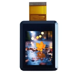
Chemical strengthening can increase surface and edge resistance without using a very thick sheet, but the outcome depends on material and process conditions. Thermally tempered glass has different fabrication and breakage characteristics. Cut-outs and sharp corners can introduce stress concentrations, so edge geometry should be reviewed before the design is frozen.
When a project specifies tempered flat glass, the supplier should state the applicable material standard, test method, and acceptance criteria. A general reference such as ASTM C1048 may be relevant, but the selected test method must match the destination market and application risk.
Account for optical bonding and air gaps
Optical bonding changes the mechanical and optical behavior of the touch-display stack. An air gap can increase internal reflections and parallax, while also creating a possible path for moisture or dust. Optical bonding may improve readability and reduce reflections, but it adds process controls for adhesive selection, cleanliness, curing, and inspection.
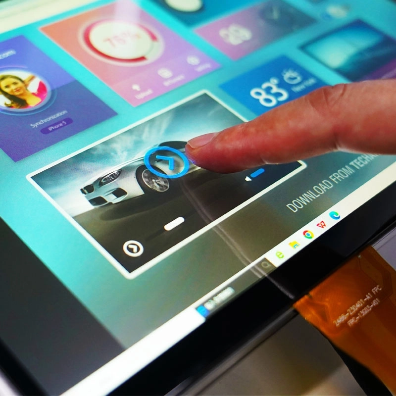
Changing cover glass thickness can affect:
- Adhesive volume and bond-line thickness
- Touch-controller tuning
- Bezel height
- LCD viewing distance
- Gasket compression
- Cable and connector clearance
- Enclosure tolerances
The supplier should provide a cross-sectional drawing that shows the cover glass, touch sensor, adhesive, LCD module, gasket, and enclosure interface. Nominal dimensions and tolerances should be recorded for every layer.
Validate the complete touch-display module
A loose glass sample does not represent the final assembly. Mechanical validation should use production-intent glass, sensor, adhesive, bezel, and enclosure parts.
A suitable qualification plan may include:
- Visual inspection for chips, scratches, bubbles, print defects, and contamination
- Touch testing across the full active area and near the edges
- Bare-finger, gloved-finger, and stylus testing where applicable
- Impact testing based on the project requirement
- Temperature cycling and humidity exposure
- Vibration testing for mobile or mechanically active equipment
- Cleaning-agent compatibility testing
- Post-test inspection for cracks, delamination, dead zones, and touch drift
For larger modules, deflection should be measured under the expected mounting load. Excessive deflection can transfer stress to the touch sensor, LCD cell, adhesive, or bezel. Mounting torque should also be controlled because uneven clamping can create local stress even when the glass is sufficiently thick.
What the supplier quotation should include
A thickness number is not enough for purchasing approval. The quotation and technical package should request:
- Complete 2D drawing and stack-up
- Glass material and strengthening method
- Thickness and dimensional tolerances
- Edge and corner specifications
- Touch technology and controller information
- Bonding method and adhesive details
- Operating and storage conditions
- Inspection criteria and sampling plan
- Impact or durability test method
- Cosmetic acceptance standard
- Packaging method
- Engineering-change notification process
- Repeat-order and batch-consistency controls
Miqi Display’s custom solutions page states that its engineering service can adjust touchscreen glass thickness and shape, add custom-cut cover glass, and use optical bonding. These capabilities are relevant to verify during quotation, drawing review, and sample approval. They should not be treated as a substitute for application-specific testing.
The Miqidisplay homepage presents the company as an LCD developer and manufacturer with custom TFT and LCD display services. For procurement, the important follow-up is to confirm which glass materials, treatments, bonding processes, drawings, inspection records, and repeat-order controls apply to the specific module under review.
Cover glass thickness selection checklist
| Decision area | Questions for the project file |
| Impact | What object, energy level, or IK target must the assembly withstand? |
| Panel size | What is the exposed span and unsupported distance? |
| Touch input | Capacitive or resistive? Are gloves or styluses required? |
| Stack-up | What are the sensor, adhesive, air-gap, and LCD dimensions? |
| Optics | Are parallax, reflection, haze, and brightness limits defined? |
| Mounting | How are the edges supported, and what torque is permitted? |
| Environment | What temperature, humidity, vibration, dust, and cleaning conditions apply? |
| Quality | Which dimensional, cosmetic, touch, and post-test criteria determine approval? |
| Supply | Are drawings, change control, packaging, and repeat-order procedures documented? |
FAQ
Is thicker cover glass always better?
No. Thicker glass can improve stiffness and impact resistance, but it may increase weight, cost, touch-stack height, and enclosure complexity. Approval should be based on complete-module test results.
What thickness should be used as a starting point?
The engineering team can compare several candidate samples, for example 0.7 mm, 1.1 mm, 1.5 mm, and 2.0 mm. The final value depends on panel size, support structure, touch method, and impact requirement.
Does optical bonding make thin glass suitable for harsh environments?
Optical bonding can improve optical performance and reduce the disadvantages of an air gap. It does not automatically make thin glass suitable for high-impact conditions. Structural support and testing remain necessary.
Should industrial touch modules use chemically strengthened or tempered glass?
The choice depends on panel size, cut-outs, edge exposure, impact risk, and manufacturing constraints. The supplier should identify the treatment process and provide relevant test documentation.
Can glass thickness be changed after the touch module is designed?
Sometimes, but a change can affect touch sensitivity, adhesive volume, bezel geometry, cable clearance, and enclosure fit. A revised drawing and new sample validation should be required.
Conclusion
The correct way to choose cover glass thickness for industrial touch screens is to define the environment, model the complete stack-up, compare candidate samples, and validate the assembled TFT LCD touch module under realistic conditions. Glass thickness should be approved together with treatment, edge design, bonding method, mounting support, touch performance, and acceptance criteria.
For a project review, contact Miqi Display with the module size, active area, touch type, interface, operating temperature, enclosure drawing, expected quantity, destination market, and required impact or cleaning tests.
Email: mary@miqidisplay.com
WhatsApp: +86 189 6801 5464; +44 07892800850