









Industrial teams often need a visible interface before the complete equipment design is finished. The challenge is finding a screen component that connects quickly to a development computer or single-board computer while still matching the mechanical, electrical, and environmental requirements of the target product.
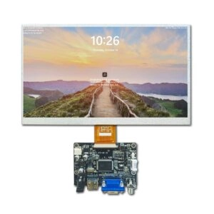
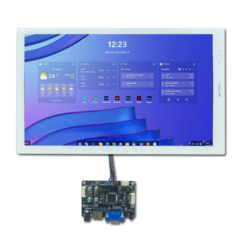
HDMI TFT LCD kits for fast industrial prototype validation can shorten this early stage by combining a TFT LCD module with a compatible HDMI signal board. The kit is used as an integration component, allowing engineering teams to test enclosure dimensions, user-interface layouts, signal behavior, touch options, and operator visibility before committing to a production design.
What an HDMI TFT LCD Kit Includes
An HDMI TFT LCD kit normally combines three elements:
- A TFT LCD panel with a defined diagonal size and resolution
- A driver or controller board that accepts HDMI input
- Cables, connectors, and sometimes optional touch hardware
The HDMI board converts the source signal into the electrical format required by the LCD panel, often through an LVDS or another panel-side interface. This arrangement allows a development computer, Raspberry Pi-class board, or embedded controller with HDMI output to display test content without requiring a custom video pipeline at the beginning of the project.
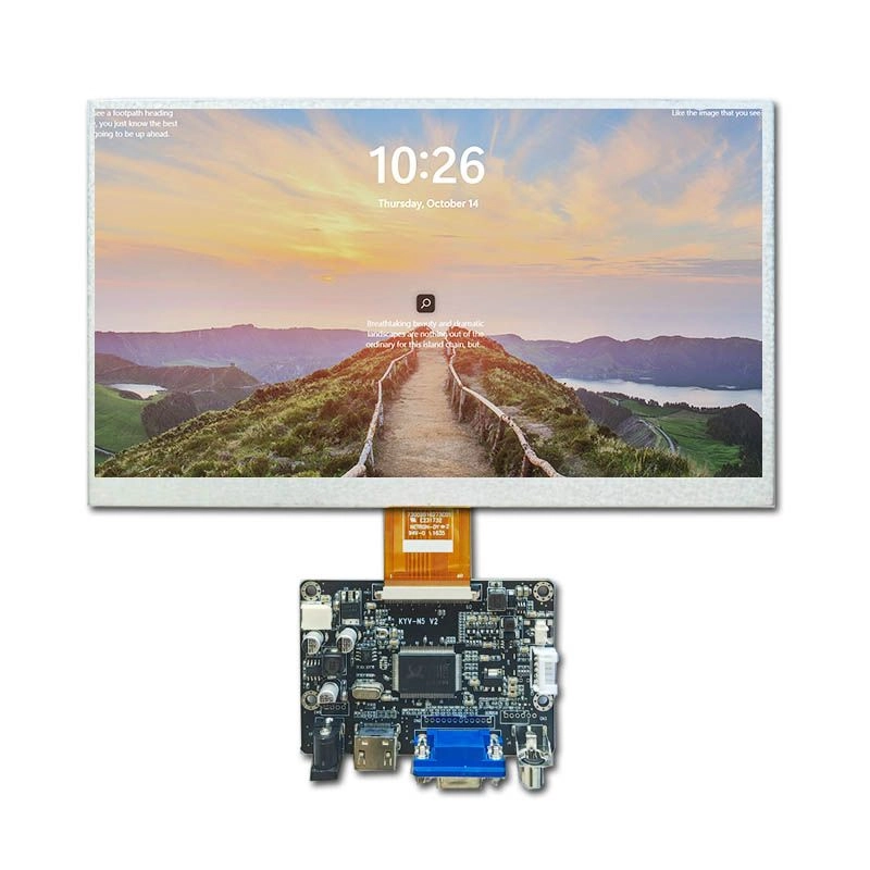
The kit remains a component for integration. It does not replace the product enclosure, control electronics, power design, or software interface that the finished industrial system will require.
A useful starting point is the current HDMI TFT Display category, where available combinations can be screened by size, resolution, interface, operating temperature, and brightness.
Why HDMI Helps During Prototype Validation
HDMI is widely available on development computers and many embedded platforms. That makes it practical for early validation activities such as:
- Checking whether the selected resolution fits the intended user interface
- Testing graphics, fonts, alarms, and data visualization
- Confirming image orientation and viewing direction
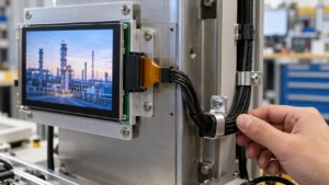
- Evaluating cable routing and connector access
- Demonstrating a concept to internal stakeholders or pilot customers
- Measuring perceived readability under representative lighting
A direct HDMI connection can also isolate display evaluation from unfinished application electronics. The engineering team can test the visual component while firmware, enclosure tooling, or the final processor board is still under development.
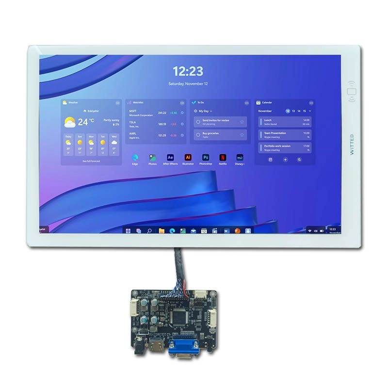
This does not eliminate compatibility work. Signal timing, supported resolutions, power input, grounding, cable length, and controller-board settings still need confirmation. A prototype that works from a laptop may require additional testing with the target embedded board.
Select the Panel Around the Prototype Decision
The correct kit depends on what the prototype must prove. A compact control interface may require a 4.3-inch or 5-inch panel, while a dashboard or machine-vision console may need 10.1 inches or more. The category currently includes examples such as 7-inch 1024×600, 10.1-inch 1024×600, 10.4-inch 1024×768, 13.3-inch 1920×1080, and 15-inch 1024×768 configurations.
Resolution should be selected according to information density and viewing distance. A higher pixel count can improve detail, but it may also affect graphics scaling, processor load, and the visual size of existing interface elements. Prototype software should therefore be tested at the panel’s native resolution rather than relying only on automatic scaling.
Brightness is another early decision. Indoor laboratory tests may be acceptable at around 300 cd/m², while equipment placed near windows or under strong task lighting may need a brighter option. Brightness alone does not determine readability; cover glass, optical bonding, surface reflections, viewing angle, and ambient light all influence the result.
Operating temperature must be treated as a system requirement. The listed HDMI category includes options such as -20°C to 70°C, -30°C to 80°C, and -30°C to 85°C. These values should be checked against the actual internal enclosure temperature, not just the surrounding room temperature. The final acceptance plan should define whether the display is evaluated during startup, continuous operation, thermal cycling, or all three.
Check Touch and Mechanical Integration Early
A prototype can appear successful on a bench and still fail during enclosure integration. Before ordering samples, the engineering package should include:
- LCD outline dimensions and active area
- Overall thickness, including the driver board
- Mounting-hole locations and bracket clearances
- Connector position and cable bend radius
- Required front-surface opening
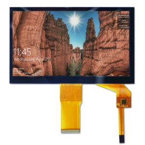
- Touch-panel type, if touch is part of the concept
- Cover-glass thickness and edge treatment
- Power-input location and acceptable voltage range
Touch should be specified separately from the LCD panel. Capacitive touch can support gesture-oriented interfaces, while resistive touch may suit gloved operation or applications that use a stylus. The choice affects cover glass, controller electronics, firmware, and industrial design.
The custom solutions page describes possible adjustments such as cable length and pin position, touch-panel add-ons, interface integration, connector changes, PCB modifications, cover glass, mounting features, and backlight parameters. These options should be treated as engineering subjects for quotation and sample approval, not assumed features of every standard kit.
Build a Repeatable Validation Sequence
Fast validation works best when the sample test is structured. A practical sequence is:
- Signal test:Connect the kit to each intended HDMI source and record recognized resolutions, startup behavior, and recovery after signal interruption.
- Image test:Display solid colors, fine lines, text at production size, gradients, and fast-moving content. Inspect for artifacts, flicker, scaling errors, or dead pixels.
- Mechanical test:Install the module in a representative frame or 3D-printed enclosure. Check access to connectors, cable strain, panel flatness, and interference with nearby components.
- Environmental test:Operate the assembly at the planned temperature range and observe brightness, color, startup time, and touch response.
- Human-factors test:Have representative operators read alarms, status values, and instructions at the intended distance and angle.
- Documentation review:Match the received sample against the drawing, specification sheet, cable definition, and revision information.
The acceptance record should identify the exact panel revision and controller-board revision. Mixing a tested LCD with a different board or cable can create results that are difficult to reproduce.
Evaluate the Supplier, Not Only the Sample
A sample demonstrates one configuration. A production decision also depends on documentation, communication, and repeatability.
Procurement and engineering teams should request:
- A complete specification sheet and dimensional drawing
- Panel and controller-board part numbers
- Supported HDMI input formats
- Power requirements and connector pinout
- Touch-controller details, when applicable
- Operating and storage temperature definitions
- Brightness measurement conditions
- Pixel-defect and cosmetic inspection criteria
- Packaging method for panel and PCB protection
- Change-notification and revision-control procedures
- Sample and production approval workflow
The supplier should also explain which items are standard and which require customization. This distinction affects tooling, engineering charges, lead time, and the ability to reproduce the validated configuration.
For projects that move from proof of concept to pilot production, Miqidisplay presents HDMI TFT modules alongside custom engineering options and states that its facilities hold TS-16949, ISO-9001, and ISO-14001 certifications on the company homepage. Those statements are useful starting evidence; the purchasing team should still confirm certificate scope, applicable product family, and the quality documents available for the specific project.
Prototype Purchase Checklist
| Decision area | Information to confirm before sample order |
| Panel size | Diagonal size, aspect ratio, active area, outline dimensions |
| Resolution | Native pixels, supported HDMI input modes, scaling behavior |
| Brightness | Typical value, measurement method, ambient-light target |
| Viewing | Viewing direction, angle requirements, reflection controls |
| Temperature | Operating and storage ranges, startup conditions |
| Touch | Capacitive or resistive, controller interface, cover-glass needs |
| Driver board | HDMI connector, power input, LVDS or panel-side connection |
| Mechanics | Mounting points, thickness, cable exit, bracket clearance |
| Quality | Pixel policy, inspection record, revision identification |
| Supply | Sample quantity, pilot quantity, change control, quotation basis |
FAQ
Are HDMI TFT LCD kits suitable for industrial equipment prototypes?
Yes, when the kit’s temperature range, brightness, mechanical dimensions, power requirements, and signal compatibility match the prototype conditions. The kit should be validated inside a representative enclosure before production approval.
Does every HDMI TFT module include touch?
No. Touch support varies by configuration. Some listed modules have no touch, while other designs can be specified with capacitive or resistive touch hardware.
Can an HDMI kit connect directly to a Raspberry Pi?
Many HDMI configurations are intended for Raspberry Pi and other single-board computers, but the supported resolution, operating-system behavior, power arrangement, and cable connection should be confirmed for the selected model.
What information should be sent when requesting a quotation?
Useful inputs include target size, native resolution, HDMI source, brightness target, operating temperature, touch requirement, mechanical drawing, annual quantity, sample quantity, and destination market.
Can the cable or connector be changed?
Some projects can use cable-length, pin-position, connector, or PCB adjustments. These changes must be reviewed against the selected LCD panel and controller-board design.
Conclusion: Move From Display Concept to Verified Module
HDMI TFT LCD kits for fast industrial prototype validation are most valuable when they are used as a controlled engineering reference. The key is to validate the complete component set: LCD panel, driver board, cable, touch layer, power input, and mechanical mounting.
For a specification review, compatibility check, or sample plan, send the target resolution, HDMI source, brightness and temperature requirements, touch preference, drawing, and expected quantities to Miqidisplay’s contact team. The discussion can then focus on a reproducible TFT LCD module configuration for the next prototype stage.