





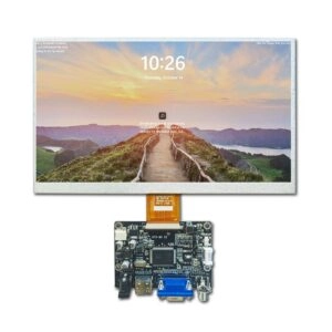
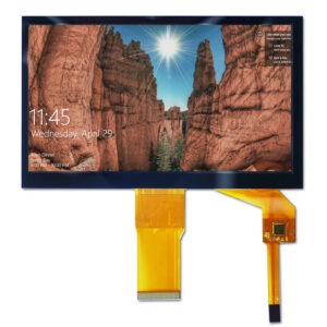
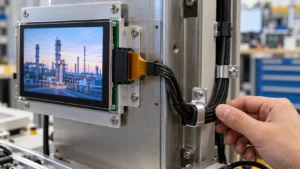




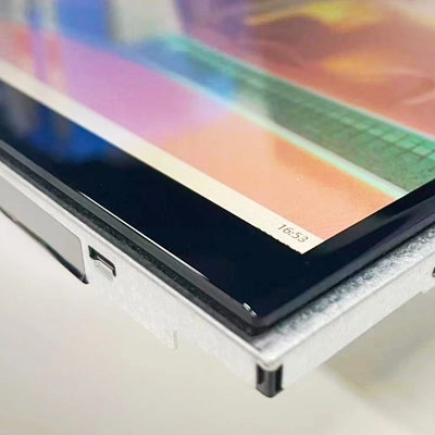
Reviewing assembly pressure before LCD sample approval prevents a common validation gap: an LCD module may perform correctly on a workbench but develop optical or functional problems after installation in the equipment housing.
A powered, unmounted sample mainly confirms basic electrical compatibility, image quality, interface operation, and initial touch response. It does not reproduce pressure from bezels, gaskets, screws, brackets, adhesives, cover glass, or enclosure tolerances. For OEM teams evaluating TFT LCD modules, approval should therefore include the production-intent mechanical stack.
A Powered Sample Is Not a Mounted Sample
During bench evaluation, the LCD module is normally placed on a flat surface or held with minimal restraint. The glass cell and backlight structure are not exposed to the same forces they will experience inside the finished equipment.
The conditions change after assembly. A gasket may be compressed, screws may pull a bracket unevenly, and a cover lens may transfer force toward the active area. Small dimensional differences between the LCD module, housing, foam, and mounting hardware can also accumulate.
As a result, a sample that appears acceptable before installation can show pressure-related mura, light leakage, local discoloration, or touch irregularities after installation. Approving the module without examining this condition leaves a system-level risk undiscovered.
How Assembly Pressure Reaches the LCD Module
Pressure does not come from screws alone. It is created by the entire mechanical stack and the way its tolerances interact.
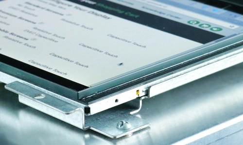
| Pressure source | Potential mechanism | Approval information required |
| Front bezel | Contacts the module or concentrates force near an edge | Contact area, clearance, flatness, and keep-out zones |
| Gasket or foam | Compression is too high or uneven | Material, thickness, compression range, and placement |
| Mounting screws | Torque or tightening sequence distorts the frame | Torque setting, screw sequence, and fastener position |
| Cover glass or touch panel | Transfers load toward the LCD cell | Stack drawing, bonding method, adhesive thickness, and gap |
| Rear bracket | Pushes against the backlight or module frame | Support points, bracket flatness, and module clearance |
| Adhesive | Shrinkage, thickness variation, or uneven placement changes the load | Adhesive type, application pattern, and cured thickness |
| Enclosure | Warpage or tolerance accumulation twists the assembly | Dimensional tolerances and production-intent samples |
Fastener torque is an important process input, but it is not a direct measurement of pressure on the LCD cell. Two assemblies using the same torque can load the module differently when bracket flatness, gasket compression, screw friction, or part tolerances vary.
What Excessive or Uneven Pressure Can Change
LCD cells are sensitive to mechanical stress. Localized force can disturb the optical behavior of the liquid crystal layer and create visible nonuniformity. Typical symptoms include:
- Bright or dark patches on uniform backgrounds
- Pressure mura near corners, edges, or fastener locations
- Local color shifts or contrast changes
- Light leakage that changes with screw torque
- Image distortion when the housing is pressed or twisted
- Temporary defects that disappear after loosening the assembly
- Touch dead zones, false inputs, or inconsistent sensitivity
- Stress on the flexible cable, connector, backlight, or bonded layers
Some symptoms appear immediately. Others become visible only after the module has warmed up, remained assembled for a period, or experienced different operating temperatures. This is why a short power-on inspection cannot represent the complete mechanical condition.
A pressure-related symptom does not automatically prove that the LCD module itself is defective. It may indicate that the module specification and the enclosure design are individually acceptable but incompatible as an assembled system.
How to Test Assembly Pressure Before LCD Sample Approval
1. Use a Production-Intent Mechanical Stack
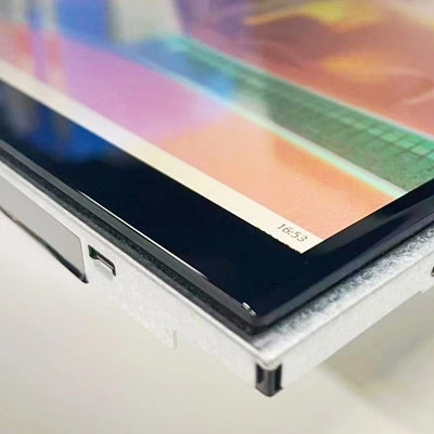
The test assembly should include the intended bezel, gasket, cover glass, touch panel, bracket, adhesives, standoffs, and screws. Temporary fixtures may not reproduce the actual load path.
If final parts are unavailable, engineering teams should document which prototype materials differ and how those differences may affect stiffness, thickness, flatness, or compression.
2. Control Torque and Tightening Sequence
A calibrated torque tool should be used when screws secure the module or its bracket. The torque value and tightening sequence must be recorded so the test can be repeated.
Testing more than one reasonable torque condition can reveal whether the design has a narrow process window. The correct setting must come from the mechanical design and fastener requirements, not from a generic LCD torque value.
3. Inspect With Diagnostic Test Patterns
Photographs of a normal interface are not sufficient for pressure evaluation. Full-screen patterns make nonuniformity easier to identify. Useful patterns include:
- Mid-gray for mura and brightness variation
- White for shadows, contamination, and dark pressure marks
- Black for light leakage
- Red, green, and blue for local color abnormalities
- Fine lines or grids for image distortion
Viewing distance, angle, ambient lighting, camera exposure, module warm-up time, and backlight setting should remain consistent. Otherwise, approval photographs will not support reliable comparisons.
4. Test the Entire Touch Area
For modules with a touch panel, the evaluation should cover the full active area, including edges and corners. Drag paths, multi-point operation where applicable, repeated taps, and idle false-touch observation can reveal assembly effects that a single center-screen tap misses.
5. Evaluate Tolerance and Temperature Effects
One carefully assembled prototype does not prove that every production unit will receive the same pressure. Module thickness, gasket thickness, housing flatness, adhesive thickness, and bracket geometry all have manufacturing tolerances.
Risk-based validation should therefore include multiple assemblies representing realistic part variation. When the application has defined operating-temperature requirements, optical and touch checks should also be repeated after suitable temperature stabilization in the assembled condition.
6. Reassemble and Repeat
The housing should be disassembled and rebuilt using the documented process. If the optical result changes significantly between assemblies, the design or assembly method may not be sufficiently repeatable for approval.
Pressure-sensitive film or other force-mapping methods can support troubleshooting when contact locations remain unclear. These tools should complement powered optical testing rather than replace it.
What the Approval Record Should Contain
An approval decision needs more than a signed sample label. The record should connect the approved LCD module to the approved assembly condition.
| Approval item | Minimum record |
| Module identity | Exact model, revision, and approved drawing |
| Mechanical stack | Housing, bezel, gasket, lens, touch panel, bracket, and adhesive details |
| Fastening process | Screw locations, torque, tool, and tightening sequence |
| Optical test | Patterns, viewing conditions, backlight setting, photos, and acceptance limits |
| Touch test | Test method, active-area coverage, and pass criteria |
| Environmental condition | Temperature and stabilization time when relevant |
| Repeatability | Number of assemblies and reassembly results based on project risk |
| Change control | Components and process parameters that require revalidation |
Approval criteria should distinguish cosmetic observations from functional failures and define which conditions are acceptable. Terms such as “no obvious mura” are difficult to enforce unless viewing conditions and reference examples are also established.
Where Supplier Input Helps
Miqidisplay presents its business around LCD screens and TFT LCD modules for integration projects. Supplier discussions at the sample stage should cover the approved module drawing, mechanical keep-out areas, touch and cover-glass stack, flexible-cable routing, and the conditions under which the sample was inspected.
The company’s custom display solutions page lists cover glass, gaskets, metal mounting brackets, threaded supports, and pressure-sensitive adhesives among its customization and mounting options. These elements should be included in the mechanical review whenever they form part of the proposed module assembly.
FAQ
Can an LCD module pass inspection before assembly and fail afterward?
Yes. Bench inspection does not reproduce force from the housing, bezel, gasket, bracket, or cover-glass stack. A module can therefore pass electrical and initial optical checks but show nonuniformity after installation.
Does reducing screw torque always solve LCD pressure mura?
No. Lower torque may reduce one source of stress, but it can also weaken retention or sealing. The actual cause may be bracket warpage, excessive gasket compression, insufficient clearance, or an incorrect support location.
Should assembly pressure be tested on a powered module?
Yes. Many pressure effects are easiest to observe while the LCD module is operating with uniform diagnostic patterns. Mechanical inspection alone cannot confirm the final optical result.
Is one assembled sample enough for approval?
Not necessarily. One sample may not represent variation in module thickness, gasket compression, housing flatness, or assembly technique. The number of validation units should be based on project risk and expected production variation.
When should pressure testing be repeated?
Revalidation should be considered after changes to the LCD module revision, housing, bezel, touch panel, cover glass, gasket, adhesive, bracket, fasteners, torque setting, or assembly sequence.
Conclusion
Reviewing assembly pressure before LCD sample approval converts a bench-level check into a system-level validation. The approval process should reproduce the intended mechanical stack, control assembly variables, inspect diagnostic patterns, verify touch performance, and document repeatable acceptance criteria.
For a project-specific sample review, contact Miqidisplay with the LCD module model or drawing, enclosure cross-section, cover-glass and touch configuration, gasket or foam specification, screw locations and torque, operating conditions, and photographs of any pressure-related symptoms.
Email: mary@miqidisplay.com
WhatsApp: +86 189 6801 5464; +44 07892800850