












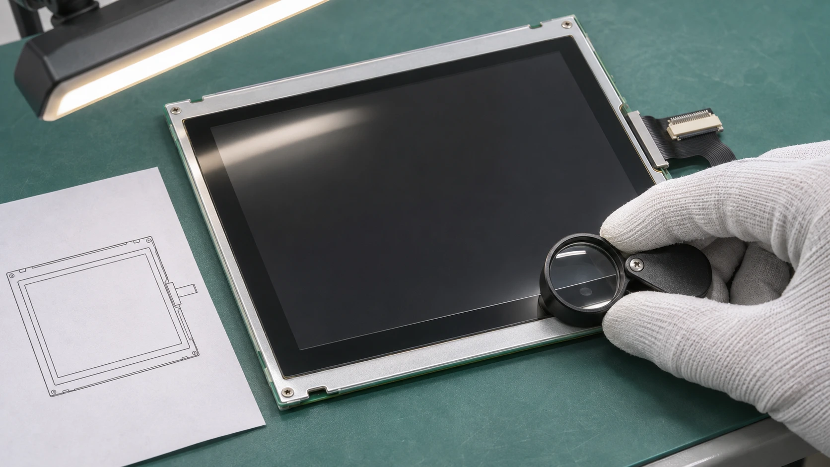
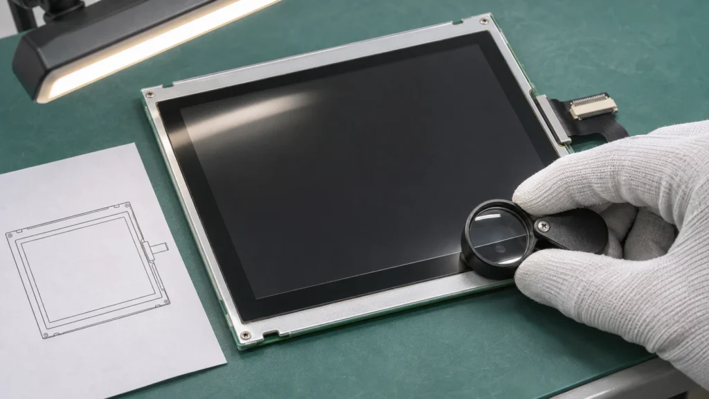
Draw the bubble acceptance zones on the optically bonded LCD assembly and cite the drawing revision on the purchase order. Each zone needs a boundary, a size and count limit, and an inspection method. A bubble beside the glass border is a good check on the wording. If the supplier calls it hidden but the receiving inspector sees it through the bezel opening, both teams need a drawing that settles which rule applies.
Draw the zones on the assembled module
Start with a front view of the module as delivered. Locate the LCD active area, the clear opening in the printed cover glass, and the adhesive footprint from the same drawing datums. Mark the viewing side and a physical orientation feature, such as the cable exit, so neither team mirrors the drawing at the inspection bench. Use a section view to identify the adhesive layer under inspection. If the stack contains two optical bonds, say whether the limits apply per layer or to their combined appearance from the front.
The active area is the pixel field. The installed viewing window is what the operator can see through the cover and bezel. On an overlay of the module and enclosure drawings, shift the parts through their allowed positions. A strip that sits under the bezel at nominal alignment may be exposed when the module or bezel shifts. Include that strip in the visible zone if any allowed assembly position exposes it.
Give each zone a clear acceptance rule
| Drawing zone | What it covers | What to put in the specification |
| A. Primary viewing area | The part of the visible window where fine text, symbols, or other critical content must remain legible | State whether any bubbles may be detected under the agreed method. If some are allowed, give size and count limits. |
| B. Visible margin, if used | A dimensioned strip within the visible window outside Zone A | Specify maximum size, maximum count per module, minimum spacing if needed, and clearance from Zone A. |
| C. Masked bonded perimeter | Bonded material that remains hidden across the permitted assembly tolerances | Specify the required bond coverage and separate rules for isolated voids, edge-connected voids, and separation. |
Use two zones if the visible window needs the same rule throughout. If you add a visible margin, dimension its width and show exactly where it ends at corners and cutouts. Review the printed cover-glass drawing when setting the masked zone. Any area classified as hidden should remain covered at the agreed viewing angles and assembly offsets. Where the print blocks the view of the bond, agree on a verification method before quoting. An image taken before the interface is obscured can document that inspection stage. If the order requires verification of the finished bond beneath the print, agree on a method that can check it at that stage.
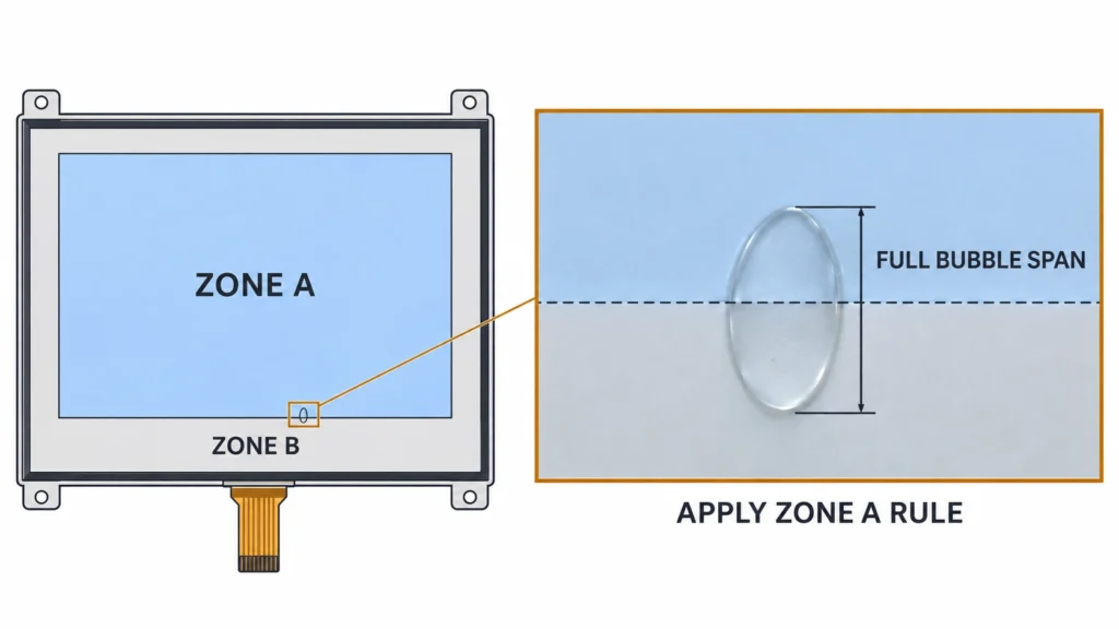
Write the boundary rule next to the zone map. Take an elongated bubble with its center in Zone B and one end in Zone A. If the drawing assigns boundary defects to the stricter zone, compare the entire bubble with the Zone A limit. Cropping the measurement at the line would give a different result. Where the drawing calls for a clearance from Zone A, measure from the nearest point of the bubble to the zone boundary.
Define how bubbles are measured and counted
Define a bubble as an enclosed void in the specified adhesive layer. Record a void open to the bond edge under the separate edge rule. Keep trapped particles, surface marks, and pixel defects in their own categories because the drawing may assign different limits to them. The cover-glass contamination guide covers the separate task of controlling particles in the stack.
For irregular bubbles, one option is to measure the longest dimension across the projected footprint in millimeters. Two touching bubbles may pass if measured separately but exceed the limit when measured as a single feature. Settle that counting rule in the specification. If you limit clusters, define spacing edge to edge and state whether a cluster is rejected or measured as a group. The drawing determines whether an individual module passes. The lot sampling plan determines how module results affect release of the shipment.
Match the inspection setup at both sites
Write the inspection sequence in the order it will be performed. For an unpowered check under reflected light, specify where the light and inspector sit relative to the module. If the module is then powered, name the image patterns and brightness setting. Set the viewing distance, allowed angles, and inspection time for each step. Specify when to use magnification for measurement. If repeated measurements fall on both sides of a limit, the procedure should say whether to remeasure with a reference setup or hold the unit for review.
State when the first inspection takes place after bonding. If qualification includes environmental exposure, identify the recovery period and compare the same locations before and after exposure. Give the supplier and the receiving team a sample with a defect close to a zone line. Have each team mark its location, measure it, and make a disposition. If their results differ, resolve whether the disagreement comes from the drawing, lighting, or measurement setup before approving the method.
Carry the agreement from RFQ to purchase order
Attach the draft zone drawing to the RFQ. Ask the supplier to identify the specific rows it can quote as written and to mark any proposed changes. An exception to the masked-perimeter coverage rule has different implications from a request to use a different inspection angle. Ask for a sample report with defect locations, dimensions, and dispositions. Keep a marked reference sample for any borderline case that proved difficult to judge, with its part number and drawing revision.
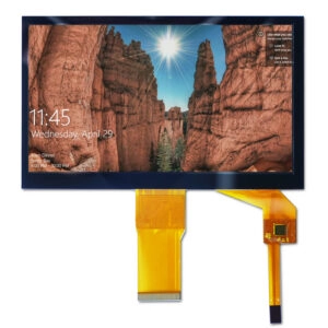
Miqidisplay’s 15-inch optically bonded LCD module example shows a configuration that combines a touch structure, cover glass, and a defined LCD active area. For a similar order, give the supplier the assembly drawing and the buyer’s bezel opening so the inspection zones can be checked against the actual stack. The OEM LCD module acceptance guide covers the broader release criteria that sit alongside this bubble specification.
Use a purchase-order note that identifies the controlling documents. One wording is “Supply the specified module revision to the approved zone drawing and visual inspection procedure listed on this order. Apply the strictest applicable zone rule to the full footprint of any bubble that touches or crosses a zone boundary. Obtain written buyer approval for exceptions before shipment.” Put the document numbers and revisions on the order and record any approved deviation against the affected lot.
Conclusion
Before releasing the order, hand the same drawing and inspection procedure to the supplier and the receiving team. If they can independently reach the same decision on a boundary sample, cite those document revisions on the order. Review the zone map again when the cover print, bond footprint, or installed opening changes.
FAQs
Can a bubble under the printed border pass?
It can pass if the drawing classifies that location as masked throughout the permitted assembly range and the defect meets the separate bond coverage and edge rules for that zone.
Can the purchase order simply say “no visible bubbles”?
Pair that wording with a defined area and inspection method. Specify the lighting, viewing conditions, and display state so the supplier and receiving inspector can apply the same detection rule.
Does a bubble limit also cover edge separation?
Give edge separation its own rule. An opening that reaches the bond edge calls for an assessment against the drawing’s bond coverage and edge criteria, even if its visible footprint is smaller than the limit for an enclosed bubble.
Request a Bubble Acceptance Review for Your Optically Bonded LCD Order
Preparing an RFQ for an optically bonded LCD module? Share your module specification, cover-glass drawing, bezel opening, and draft bubble acceptance zones with Miqidisplay. Include your expected order quantity and any mounting or operating constraints. Request a technical review to check how the proposed zones can be inspected on the assembled module and agree on what the supplier’s sample report should document before you release the purchase order.
Email: mary@miqidisplay.com
WhatsApp: +86 189 6801 5464