






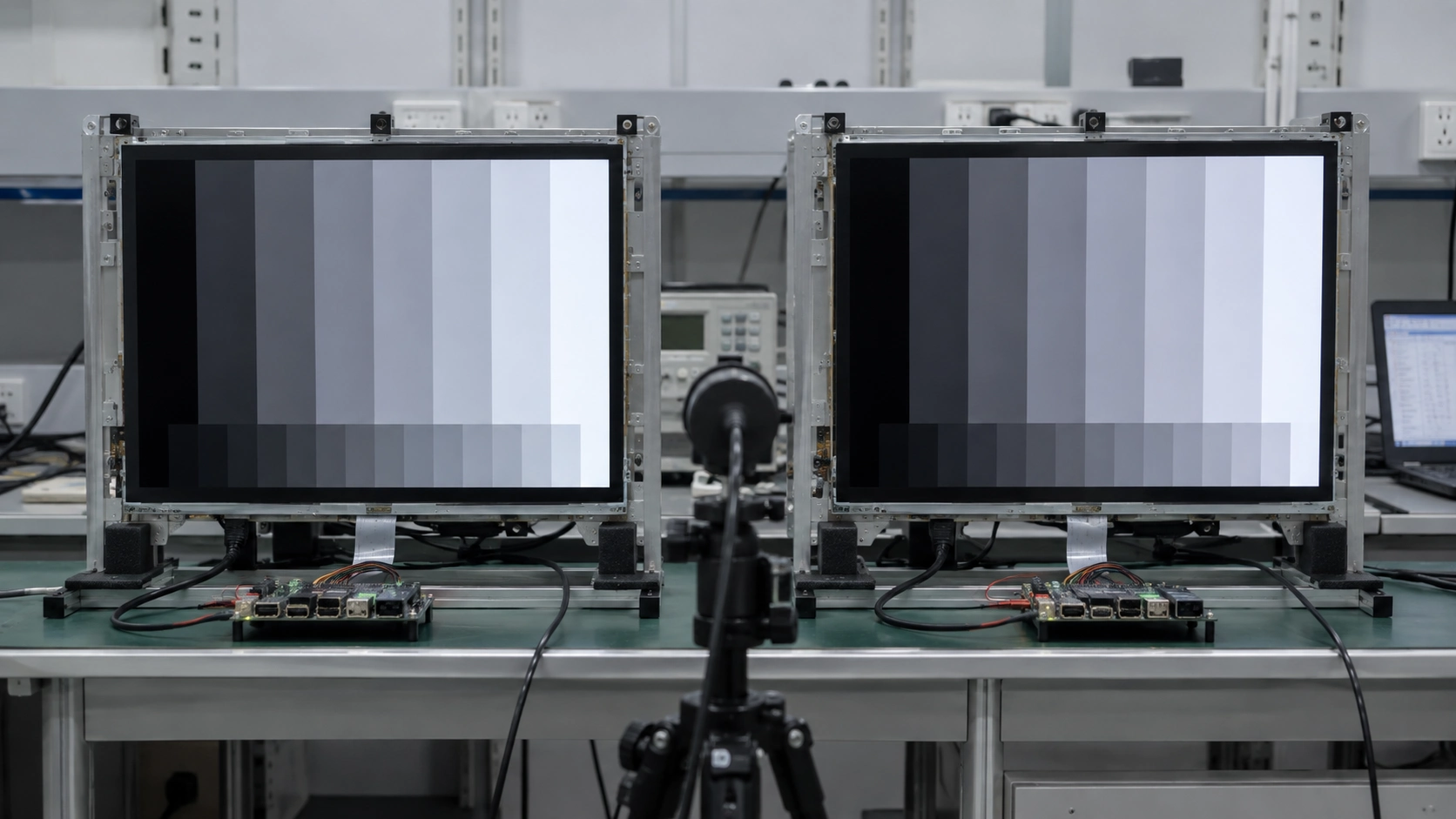
Comparing LCD samples is useful only when the setup is controlled tightly enough that the samples, rather than the environment, explain the result. Use the same fixture, electronics, image content, stabilization time, and measurement sequence for every candidate.
Why identical conditions matter
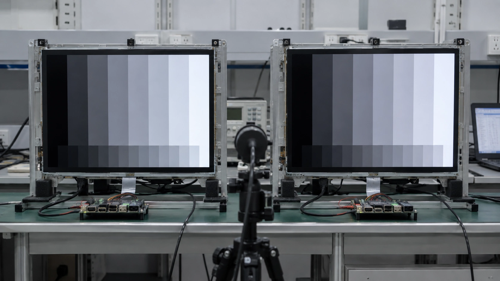
An LCD module does not show a fixed result independent of its surroundings. Brightness can change with drive settings, warm-up time, supply behavior, viewing direction, cover glass, ambient light, and mounting. A sample that looks brighter on a bench may simply be receiving a different signal or viewing geometry. Decide whether the comparison concerns a panel revision, source, touch configuration, or customized stack, and define pass criteria before testing.
Separate three decisions:
- Equivalence:do both samples meet the same drawing and interface definition?
- Performance:do they produce comparable optical and functional results under one setup?
- Integration risk:will either sample create a mechanical, electrical, or environmental issue in the target equipment?
Lock sample identity and the test hardware
Before applying power, create a record for every sample: part number, revision or date code, serial or lot reference, size, resolution, interface, touch configuration, cable, cover glass, and bracket. Photograph labels and connector orientation for traceability.
Use one approved host setup. Keep the controller, firmware, image timing, cable length, power supply, grounding, and software settings unchanged. If an adapter is unavoidable, document it and confirm that it does not alter signal, voltage, or scaling. Drive each module at native resolution with the same timing whenever the interface permits.
For a concrete reference, a 15.6-inch industrial LCD module lists 1920×1080, LVDS, 1000 cd/m², and -30°C to 85°C. Verify actual samples against the project specification.
Standardize the environment before testing
Write the conditions at the top of the test sheet. Record temperature, humidity when relevant, ambient illumination, instrument model and position, viewing angle, power input, image pattern, and warm-up time. Keep lighting stable and prevent reflections from favoring one sample.
Mount all samples using the same reference plane and support points. Do not press the glass, twist the frame, or let a cable pull the module sideways. If the product uses a cover glass, gasket, bezel, or optical stack, include it for every sample.
Choose one stabilization rule, such as a fixed elapsed time or stable reading threshold, and apply it to every unit. If the project spans temperature extremes, repeat the comparison at the relevant operating points rather than mixing room-temperature and environmental results.
Use one test sequence and one set of patterns
Run the samples in a fixed sequence so that every unit receives the same exposure. A useful order is:
- Confirm identity, connector orientation, and physical condition.
- Verify power-on behavior, image initialization, and native resolution.
- Display black, white, red, green, blue, and gray patterns.
- Measure brightness and uniformity at the same points.
- Check contrast, grayscale steps, color appearance, and viewing direction.
- Exercise the required interface and any touch function in the same application state.
- Repeat power cycling and record recovery behavior.
Use generated test patterns or controlled image files. White can reveal luminance variation; black and gray can expose leakage, mura, or nonuniform backlight behavior; color fields identify channel or calibration differences; fine lines and text show scaling and resolution behavior. Keep file format, scaling mode, and graphics pipeline constant.
Do not let a visual impression become a pass/fail decision. Two modules can look similar at the center while differing at corners or at the required viewing direction. Mark each observation with location, pattern, and condition. If a defect appears only after mounting, repeat the observation with the assembly configuration recorded.
Measure the criteria that affect the application
Follow the product specification, not a generic score. Typical criteria include:
- Luminance:measure at defined points with the same instrument geometry and state whether the backlight setting is fixed or adjustable.
- Uniformity:use the same grid and calculation method for every sample. Record the lowest and highest relevant readings, not only a center value.
- Contrast and grayscale:use identical patterns and viewing direction. Note whether dark details remain distinguishable at the intended brightness.
- Color appearance:compare controlled patches under fixed settings. If accuracy is critical, use a calibrated instrument and state the color space and project tolerance.
- Viewing direction:evaluate the angles that matter in the enclosure. A wide nominal angle does not automatically mean equal readability from every position.
- Response and stability:observe image transitions, flicker, startup, and repeated power cycles with the same timing and host electronics.
- Mechanical compatibility:check outline dimensions, active-area position, thickness, mounting points, connector access, and cable bend radius in the intended fixture.
When a measurement is outside range, first check the instrument, cable, scaling, power, warm-up state, and mounting pressure. Record the retest and its reason to protect the comparison from false failures and undocumented exceptions.
Normalize results and decide with evidence
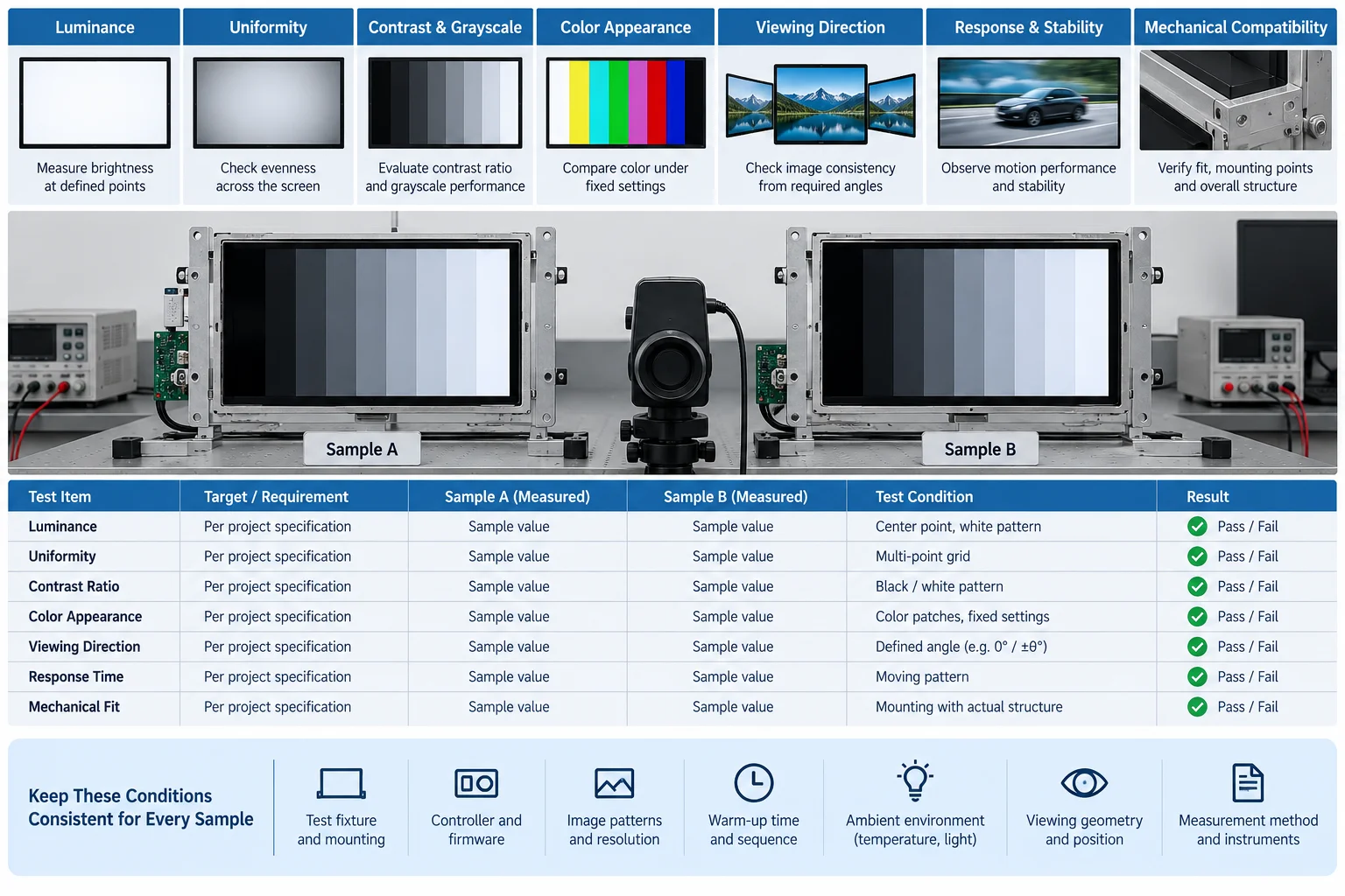
Create one comparison matrix with criteria as rows and samples as columns. Include target, measured value, condition, tolerance where available, and status. Pass, conditional review, or fail is easier to audit than a weighted score that hides incompatibility.
Compare like with like. If one sample has a different cable, cover glass, firmware, or backlight setting, either bring the configuration into alignment or mark the result as non-equivalent. Do not average away a critical issue such as an incorrect connector, an active-area offset, or unstable startup. A small optical difference may be acceptable in one application and unacceptable in another, so the decision rule must come from the product requirement.
Keep raw readings, photos, pattern files, fixture details, and revision-controlled drawings with the matrix so a supplier and buyer can reproduce the test when a configuration changes.
Move from comparison to sourcing
Once conditions are fixed, ask the supplier which items are standard and which are customized. A TFT LCD display category can help identify formats, while custom display solutions may cover project-specific changes. The comparison should use a project drawing and defined method. Document any cable, touch, connector, cover-glass, mounting, or backlight change before requesting new samples.
Miqidisplay presents LCD and TFT display modules for OEM integration and describes customization options relevant to controlled comparison. Capability, evidence, and configuration should be confirmed for the specific project. Ask which exact configuration can be reproduced under the same conditions and supported by controlled records.
Conclusion
The most reliable LCD sample comparison identifies exact units, freezes the host setup, standardizes the environment, runs one pattern sequence, measures relevant criteria, and preserves raw evidence. It separates module differences from test variation.
FAQs
What is the most important control when comparing LCD samples?
Keep the signal chain and mechanical setup identical. The same controller, timing, cable, power source, fixture, image patterns, viewing geometry, and warm-up rule should be used for every sample.
Should LCD samples be tested in the final enclosure?
Yes, when the enclosure affects pressure, reflections, viewing direction, thermal behavior, or cable routing. If the final enclosure is not ready, use a documented fixture and repeat critical checks after assembly.
How many measurements should be taken across an LCD module?
Use a repeatable grid appropriate to the active area and project risk. The important requirement is that every sample uses the same points, instrument geometry, pattern, and calculation method.
Can visual inspection replace instrument measurements?
No. Visual inspection can identify obvious artifacts, but brightness, uniformity, contrast, and color decisions should use defined measurements whenever those values affect the product requirement.
What should be sent to a supplier before requesting comparison samples?
Provide the display type, diagonal size, outline and active-area dimensions, resolution, interface, touch requirement, brightness target, viewing direction, operating temperature, mechanical constraints, quantity, drawings, and integration environment.
Request a controlled LCD sample review
For a B2B sourcing assessment, request a Miqidisplay technical fit review with the sample identity, test matrix, display type, size, outline dimensions, active area, resolution, interface, touch requirement, brightness, viewing direction, operating temperature, mechanical constraints, quantity, drawings, and integration environment.
Those inputs enable Miqidisplay to assess component compatibility, the scope of customization, the sample and documentation needed, and how comparison results can be tied to a repeatable configuration. Any price, batch, timing, certification, or performance conclusion should be confirmed against the final specification.