






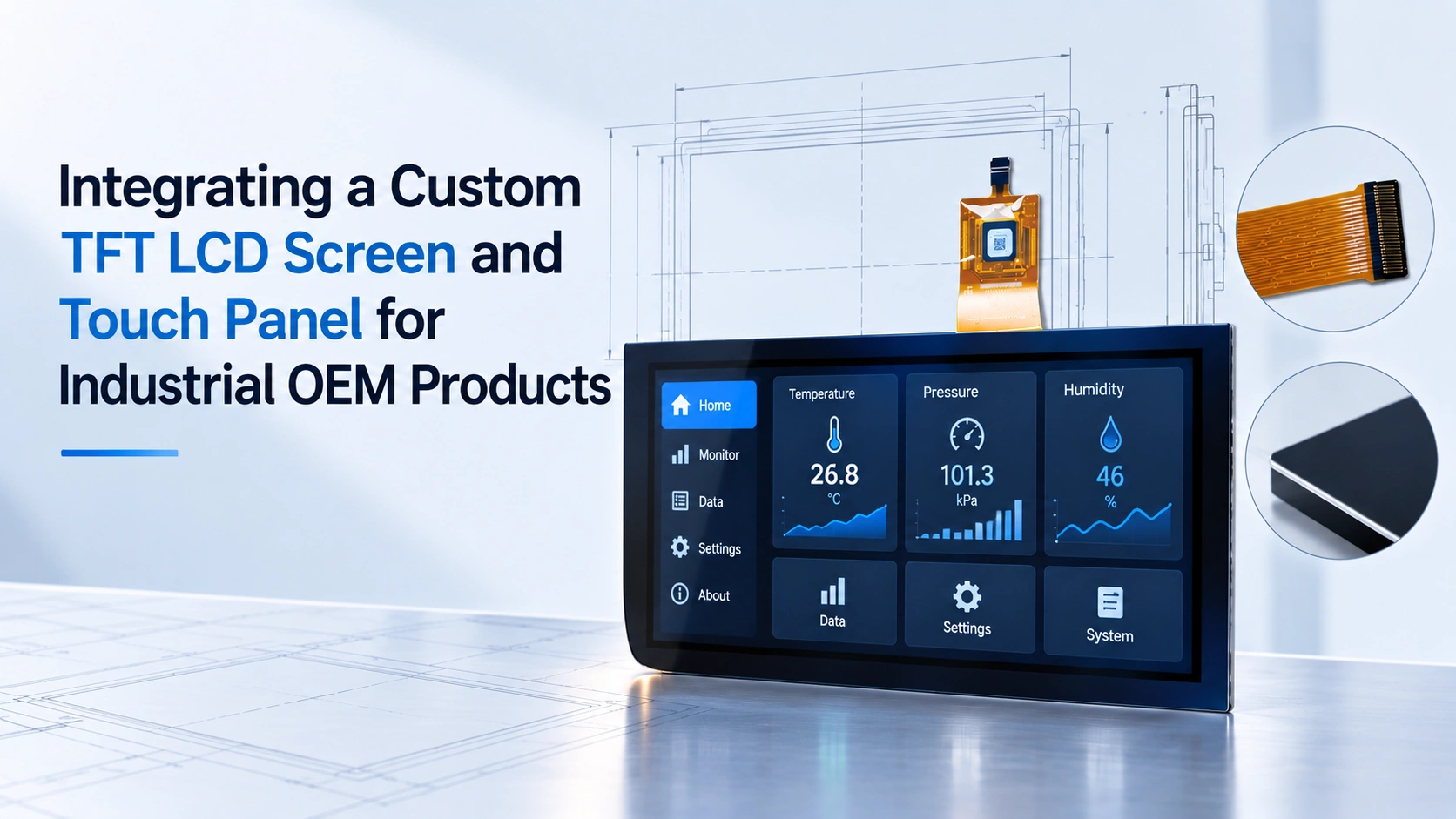
Industrial OEM equipment often requires a display module that fits a specific enclosure, supports a defined user input method, and remains stable across the application’s operating conditions. Selecting a custom TFT LCD screen and touch panel as a matched component can reduce mechanical redesign, interface conflicts, and late-stage validation problems.
The purchasing decision should therefore begin with the complete integration requirement, rather than with screen size or unit price alone. Engineering and sourcing teams need to define the LCD, touch sensor, controller, cover lens, cable, mounting method, and host interface as one system.
Define the Application Before Selecting the Module
The first step is to document how operators will interact with the equipment and where the module will be installed. Important inputs include:
- Enclosure opening and maximum assembly thickness
- Active area and preferred aspect ratio
- Viewing distance and viewing direction
- Indoor, outdoor, or mixed lighting
- Glove type and expected touch pressure
- Exposure to moisture, dust, vibration, or cleaning chemicals
- Host processor, operating system, and available interfaces
- Annual volume, sampling needs, and expected product lifecycle
A display that appears suitable in a catalog may still fail after installation if the flexible cable bends against the enclosure, the connector faces the wrong direction, or the cover lens changes the touch response.
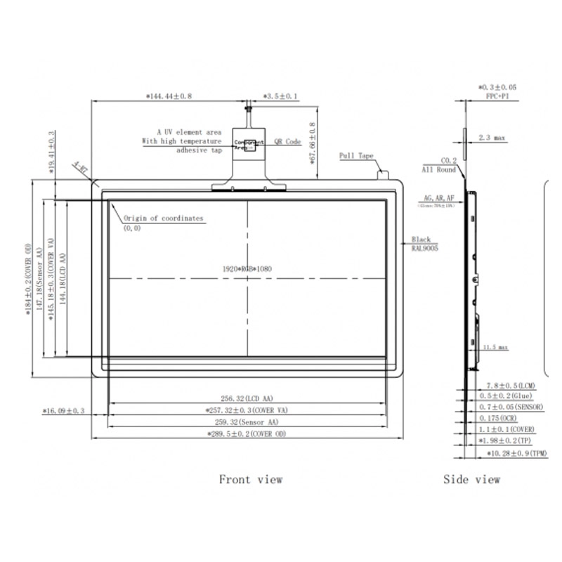
A practical specification package should include a mechanical drawing, display active area, outline dimensions, mounting-hole positions, connector details, cable length, and acceptable tolerance limits. These documents allow the supplier to confirm whether an existing module can be adapted or whether a new design is required.
Match LCD Performance to the Operating Environment
The LCD specification should be connected to a measurable use condition.
Resolution must support the smallest text, icons, or diagrams shown by the equipment software. Higher resolution is not automatically better if it increases processing, memory, or interface requirements without improving usability.
Brightness should be selected against ambient light and optical losses from the touch stack. A module used near windows or in outdoor service may require a different brightness target from one installed inside a protected cabinet. The final test should be performed through the intended cover lens and bonding structure.
Viewing angle also requires application-specific confirmation. Wide-angle IPS technology can help when operators view the equipment from different positions, but the team should still evaluate contrast and color behavior at the actual installation angle.
Temperature requirements should cover storage, transportation, startup, and continuous operation. The supplier should identify the rated limits of the LCD, touch sensor, controller, adhesive, and cable assembly separately. A single temperature figure for the overall product may hide a weaker component.
Choose the Touch Technology and Stack-Up
Projected capacitive touch is commonly selected for gesture input, smooth glass surfaces, and multi-touch interaction. Resistive touch can be appropriate when the interface must respond to pressure, a stylus, or thick insulating gloves. The decision should be based on the operator workflow rather than on technology preference.
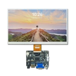
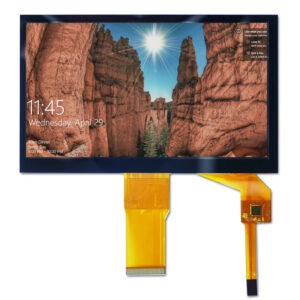
A TFT LCD touchscreen module normally includes more than the LCD cell. The complete assembly may contain a touch sensor, cover lens, optical adhesive, controller, flexible cable, and sometimes a driver board. Each added layer can affect reflectance, thickness, touch sensitivity, weight, and assembly yield.
For capacitive touch, the specification should identify the required touch points, glove material and thickness, wet-finger conditions, minimum target size, edge accuracy, and acceptable false-touch rate. For resistive touch, the test plan should define actuation force, stylus size, coordinate accuracy, and expected single-point behavior.
Cover-lens details also need early agreement. Glass thickness, edge shape, printed border, surface coating, and bonding method affect both mechanical fit and optical performance. If the equipment uses a bezel or gasket, the drawing should show the visible area and the compression zone so that the touch sensor is not accidentally loaded during assembly.
Confirm Interfaces and Electrical Compatibility
A touch panel and LCD can be mechanically compatible but electrically unsuitable. The host system may require RGB, LVDS, MIPI, SPI, USB, or I2C connections, depending on the module and controller architecture. Interface selection should be confirmed against the processor, software drivers, signal timing, voltage levels, and available board space.
The purchasing team should request:
- LCD interface and timing information
- Touch-controller protocol and driver requirements
- Connector part numbers and pin assignments
- Supply voltage and current ranges
- Backlight input and dimming method
- Reset, interrupt, and grounding recommendations
- Initialization code or command sequences where applicable
- Cable drawings and minimum bend-radius guidance
An interface change late in development can require a new controller board, firmware work, and another round of electromagnetic compatibility testing. Interface confirmation before sampling is therefore one of the lowest-cost ways to reduce schedule risk.
Validate Samples in the Final Enclosure
A sample should be evaluated as an integrated assembly, not only as a loose panel on a laboratory bench. The validation fixture should reproduce the production bezel, gasket, cable routing, host electronics, and intended power conditions.
The test plan can include:
- Mechanical fit and mounting repeatability
- Image quality at normal and off-axis viewing positions
- Touch accuracy across the center, edges, and corners
- Glove, stylus, and wet-touch behavior where relevant
- Startup, sleep, wake, and brightness-control behavior
- Temperature exposure appropriate to the application
- Vibration or handling checks when required by the equipment
- Surface inspection for bubbles, particles, scratches, and uneven bonding
- Cable and connector retention after repeated assembly cycles
The sample approval record should identify the exact revision, drawing, firmware or controller version, cosmetic limits, and test conditions. Without a controlled reference sample, production batches can drift while still appearing superficially similar.
Evaluate the Supplier’s Engineering and Quality Evidence
A suitable touch panel supplier should be able to explain how requirements move from an initial drawing to a controlled production specification. Useful evidence includes design-review records, engineering change procedures, inspection points, traceability practices, and a clear process for handling nonconforming units.
Customization may involve cable routing, connector changes, cover-lens geometry, printed masks, surface treatments, mounting features, backlight parameters, or touch-controller selection. Each change should be documented with its effect on cost, tooling, validation, and lead time.
Commercial evaluation should also cover sample quantity, minimum order assumptions, packaging, shipping conditions, forecast visibility, repeat-order controls, and end-of-life notification practices. These questions help distinguish a catalog reseller from a supplier capable of supporting an OEM product through multiple production stages.
Where a Custom Display Partner Fits
Miqidisplay presents industrial touch panels that include capacitive and resistive technologies, with listed examples covering different sizes, resolutions, interfaces, and operating ranges. Its customized display solutions include cabling, touch expansion modules, interface modifications, cover glass, mounting methods, and backlight adjustment.
For an OEM project, these capabilities should still be converted into project-specific evidence: a reviewed drawing, interface confirmation, sample plan, acceptance criteria, and quotation based on the actual quantity and destination. The company information page can be used as a starting point for reviewing the stated engineering and quality resources, while final approval should rely on documents applicable to the selected module.
OEM Specification and Sourcing Checklist
| Decision area | Information to freeze before quotation |
| LCD format | Size, active area, resolution, aspect ratio, viewing direction |
| Optical target | Brightness, contrast expectations, viewing angle, cover-lens impact |
| Touch input | Capacitive or resistive, touch points, glove, stylus, wet operation |
| Mechanics | Outline, thickness, mounting, cable exit, bezel and gasket interface |
| Electronics | LCD interface, touch protocol, voltage, backlight control, connector |
| Environment | Operating and storage temperatures, moisture, vibration, cleaning exposure |
| Validation | Sample fixture, touch test method, cosmetic limits, revision control |
| Supply | Sample quantity, forecast, batch controls, packaging, repeat-order process |
FAQ
Can the LCD and touch panel be sourced separately?
They can, but separate sourcing transfers compatibility risk to the OEM team. A matched assembly can simplify mechanical, optical, and controller validation, provided the supplier supplies complete drawings and test information.
Which touch technology is better for industrial equipment?
Neither technology is universally better. Capacitive touch is often suited to gesture-oriented interfaces, while resistive touch can be practical for pressure input, stylus use, or thick gloves. Final selection should follow testing with the real enclosure and operator inputs.
What information is needed to request a sample?
A useful sample request includes the opening size, active area, resolution, interface, touch method, cover-lens requirements, cable direction, operating conditions, host platform, and expected quantity.
How should batch consistency be checked?
The approved sample should become the controlled reference. Production inspection should compare dimensions, optical appearance, touch performance, connector details, and firmware or controller revision against that reference.
Is a custom touchscreen display always a new design?
No. A supplier may adapt an existing LCD and touch combination through cable, connector, cover-lens, mounting, or backlight changes. A new design is more likely when the required geometry, interface, or environmental conditions fall outside available modules.
Conclusion: Move From Screen Selection to Controlled Integration
A reliable industrial OEM display project starts with a complete requirement set and ends with a validated assembly. Mechanical drawings, optical targets, touch behavior, electrical interfaces, environmental limits, sample testing, and batch controls should be agreed before production approval.
For a specification review or sample-planning discussion, Miqidisplay can be approached through its contact page. The inquiry should include the LCD opening, active area, resolution, touch technology, interface, cover-lens requirements, operating conditions, sample quantity, annual volume, and delivery destination so that the next engineering and quotation steps are based on the actual project.