











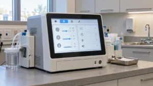

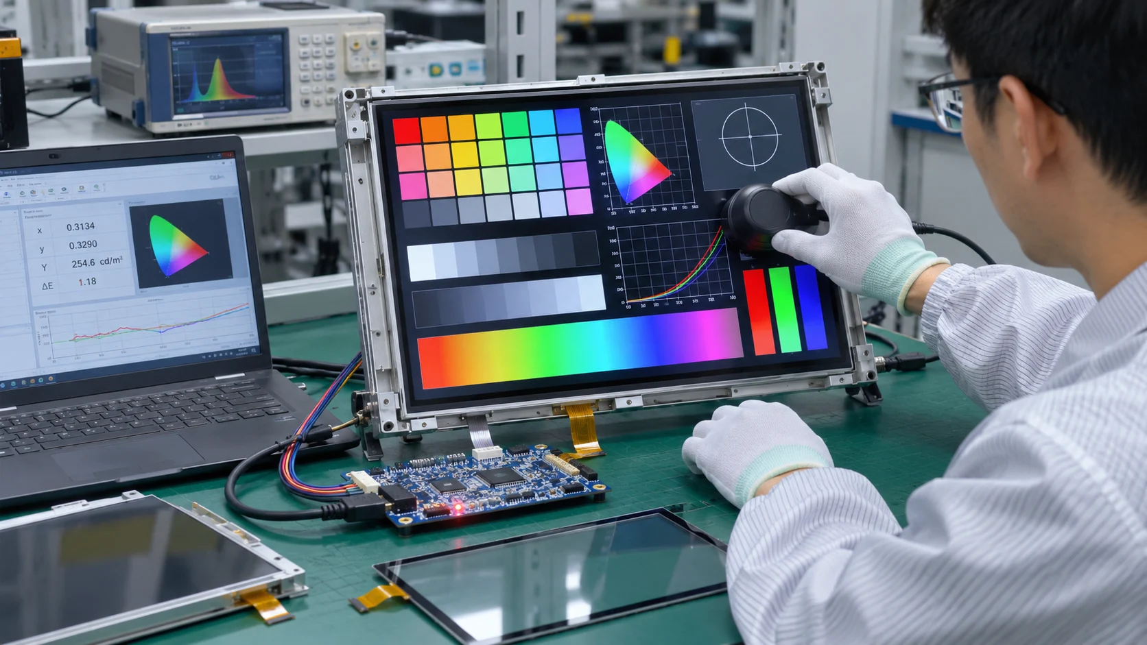
TFT LCD color calibration should be defined before a display module is approved for an embedded industrial instrument. Buyers need measurable optical targets, an agreed correction method, and repeatable acceptance conditions. A sample that looks satisfactory on a demonstration board may produce different results when connected to the instrument’s electronics or installed behind its intended cover glass.
Start with a calibration requirements package that connects the display module, host graphics, initialization settings, and optical assembly. This gives engineering and procurement teams a practical basis for comparing supplier proposals, approving samples, and controlling changes during production.
Define Which Colors Matter to the Instrument
Begin with the instrument’s actual graphics. Numerical readings, warning indicators, trend lines, neutral backgrounds, and measurement maps place different demands on a display. A screen using a few distinct status colors may need different controls from one presenting gradual changes across a colored scale.
Identify which differences could affect interpretation and which are primarily cosmetic. Where recognition matters, support color with text, symbols, or position.
Separate three requirements in the purchasing specification:
- Accuracy against a defined reference.
- Consistency between individual modules.
- Uniformity across the screen and intended viewing positions.
Each requires different evidence. Matching two samples does not establish reference accuracy, while a satisfactory center reading does not establish whole-screen uniformity. Keep these distinctions visible when reviewing supplier test reports.
Turn Color Expectations into Optical Specifications
“Accurate color” and “match the sample” leave too much room for interpretation. Define targets, permitted variation, and the conditions under which each requirement applies.
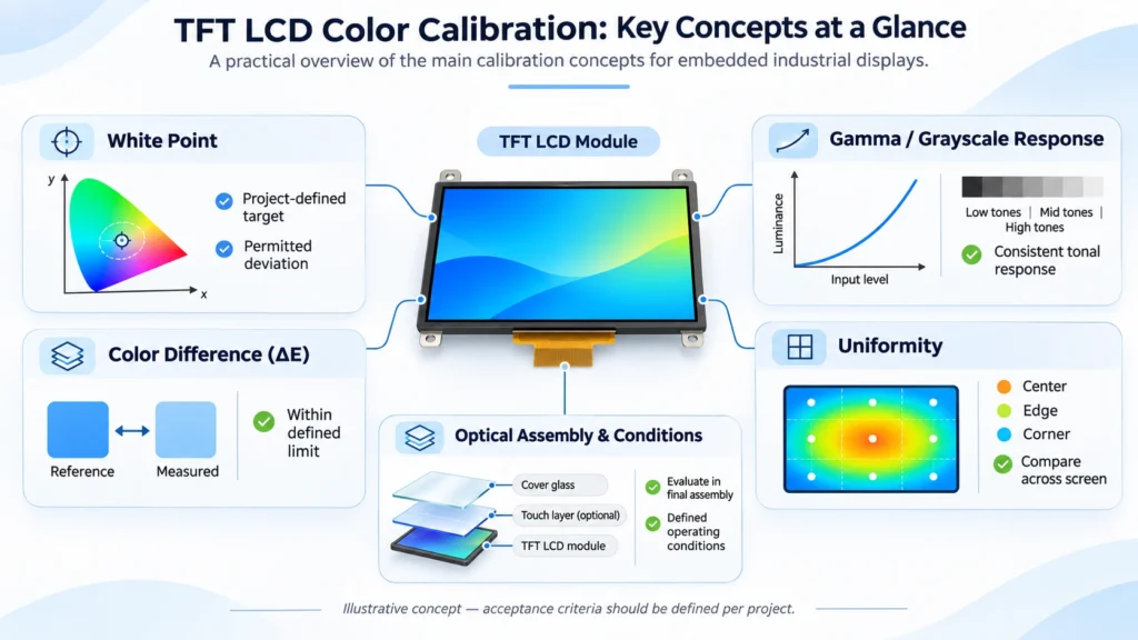
| Parameter | Information needed for acceptance |
| White point | Target chromaticity and permitted deviation |
| Luminance | Required output at the agreed operating setting |
| Grayscale response | Target response and measurement points |
| Color difference | Reference patches, calculation method, and limits |
| Uniformity | Screen locations and evaluation method |
| Viewing conditions | Direction, angle, temperature, and ambient light |
Color temperature alone does not fully describe white appearance. When neutral backgrounds must match, include chromaticity requirements. Likewise, a color-difference limit needs an identified calculation method and reference patch set.
Include positions near the edges and corners when uniform appearance matters. A center measurement can meet its target while the border remains visibly different. Distinguish spatial variation from a whole-screen color offset before deciding whether global correction is appropriate.
Establish Where Correction Will Occur
Depending on the architecture, correction may be available through display-driver settings, controller processing, or lookup tables in the host graphics path. Verify the available controls against the selected components and their documentation.
Ask whether the proposal uses one shared configuration or individual module calibration. A shared configuration reduces programming and recordkeeping complexity, but its suitability depends on demonstrated production variation. Individual calibration adds measurement, identification, data storage, and configuration-control requirements.
Assign responsibility for generating, approving, loading, and retaining correction data. Also define how the instrument identifies the correct data after startup or a software update.
Initialization settings belong in this discussion. Where software programming is included in a module project, record the initialization-code revision and ask which settings affect optical output. Programming capability alone does not prove support for adjustable gamma, white balance, or stored calibration tables.
Check Gamma and the Complete Graphics Path
Gamma describes the relationship between digital input and displayed luminance. An unsuitable response can obscure distinctions between dark shades or change the appearance of gradients even when full white appears acceptable.
Evaluate grayscale tracking alongside representative colors during TFT LCD color calibration. Select the target response around the graphics pipeline and intended visual task rather than adopting a familiar value without checking its suitability.
Before adjusting optical settings, document pixel format, RGB channel order, input range, and existing color transformations. Otherwise, calibration may compensate for a configuration error that disappears after a firmware change.
Confirm that overlapping correction stages are intentional. Record the approved register settings or lookup-table version together with the host software used for testing. A configuration that cannot be reproduced is a weak basis for production acceptance.
Evaluate the Intended Optical Assembly
The required result is the image seen through the instrument’s viewing surface. Touch glass, cover glass, adhesive, and surface treatments may change the optical result compared with a bare module.
Use an assembly representative of production for final evaluation. If early testing uses a different stack, document the difference and reserve final optical approval until the intended assembly is available.
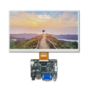
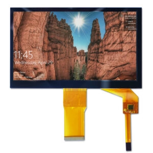
Miqidisplay’s 7-inch RGB display module offers a sourcing reference with a published 1024 × 600 resolution and capacitive touch configuration. These features support an initial compatibility review; they do not establish a calibrated color tolerance.
Similarly, assess IPS TFT display options at the instrument’s intended viewing positions. Panel technology does not replace application-specific optical acceptance.
Make Reference-Sample Comparisons Repeatable
A customer reference sample is useful only when its operating conditions are understood. Record its drive board, brightness setting, displayed pattern, correction configuration, and optical assembly before requesting a match.
Measure the reference and proposed module under comparable conditions. A visible difference should be quantified before either sample becomes the purchasing standard.
Agree on a test instruction covering:
- Module identification and hardware revision.
- Host board, firmware, and initialization versions.
- Supply conditions and brightness setting.
- Stabilization procedure and ambient temperature.
- Patch values, measurement positions, and instrument geometry.
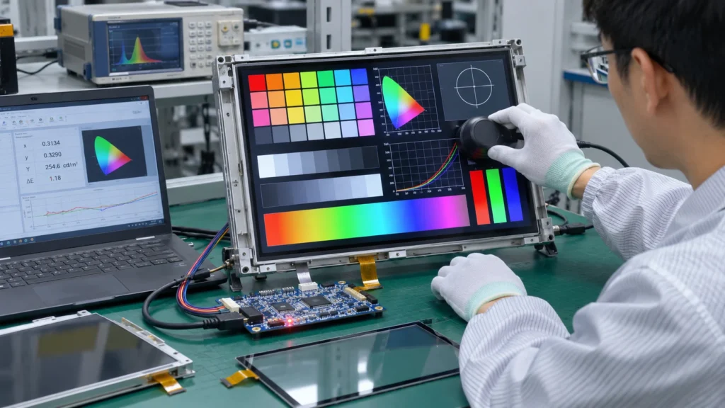
Use an optical measurement instrument suitable for the required accuracy, with its calibration status documented. Photographs can show the arrangement, but exposure and camera white balance make them unsuitable as the sole acceptance evidence.
Keep measured values with the approved reference sample and configuration record.
Test Operating Conditions and Correction Limits
Room-temperature results at one brightness setting may not represent the instrument’s operating range. Select qualification conditions around the application, including representative dimming settings and relevant temperatures within the proposed module’s specified limits.
Allow the assembly to stabilize before comparing measurements. Define whether acceptance applies at one reference condition or across several operating conditions; these are different supplier commitments.
Correction also has practical limits. It cannot create colors outside the available gamut, and one global adjustment cannot fully remove spatial nonuniformity. Channel balancing may reduce available luminance, while aggressive correction can reduce useful tonal distinctions.
If meeting the color target compromises another essential requirement, reconsider the module or optical assembly before freezing the design.
Put Calibration Responsibilities into the RFQ
Send suppliers the optical requirements alongside electrical and mechanical drawings. Include representative graphics, reference-sample conditions, the intended optical stack, correction responsibilities, and proposed acceptance methods.
Ask suppliers to distinguish standard specifications from optional work and requirements needing sample evaluation. Request applicable evidence before accepting claims about individual calibration or production color control.
Miqidisplay’s display customization options provide a starting point for discussing relevant module changes. Confirm the proposed project’s initialization settings, correction access, sample requirements, and documentation separately.
For production, define traceability, inspection sampling, and change-notification triggers. Changes to the panel, optical materials, controller settings, or initialization code should receive an optical-impact review before acceptance.
Conclusion
A useful calibration specification connects visual requirements with measurable limits, reproducible settings, and clear supplier responsibilities. Approve the intended assembly under documented conditions, then retain the configuration and measurement records needed to evaluate subsequent production.
FAQs
Does every industrial TFT LCD module need individual calibration?
No. The decision depends on the application’s tolerance and the variation demonstrated by representative samples. Some projects can use a shared configuration.
Is initialization-code programming the same as color calibration?
No. Initialization establishes operating settings. Whether those settings provide useful optical adjustment must be verified for the selected module and controller.
Can white-point adjustment correct uneven screen color?
A global adjustment changes the overall response. It does not necessarily correct differences between the center, edges, and corners.
When should optical qualification be repeated?
Review changes affecting the panel, optical stack, graphics processing, or initialization settings. Define requalification triggers before production approval.
Request a Miqidisplay Technical Fit Review
Engineering and procurement teams can request a Miqidisplay technical fit review with the display type, diagonal size, outline dimensions, active area, resolution, interface, touch requirement, brightness, viewing direction, operating temperature, mechanical constraints, quantity, drawings, and integration environment. Include color targets and reference-sample conditions so component compatibility, possible customization scope, sample evaluation, and documentation needs can be assessed before quotation acceptance.
Email: mary@miqidisplay.com
WhatsApp: +86 189 6801 5464