








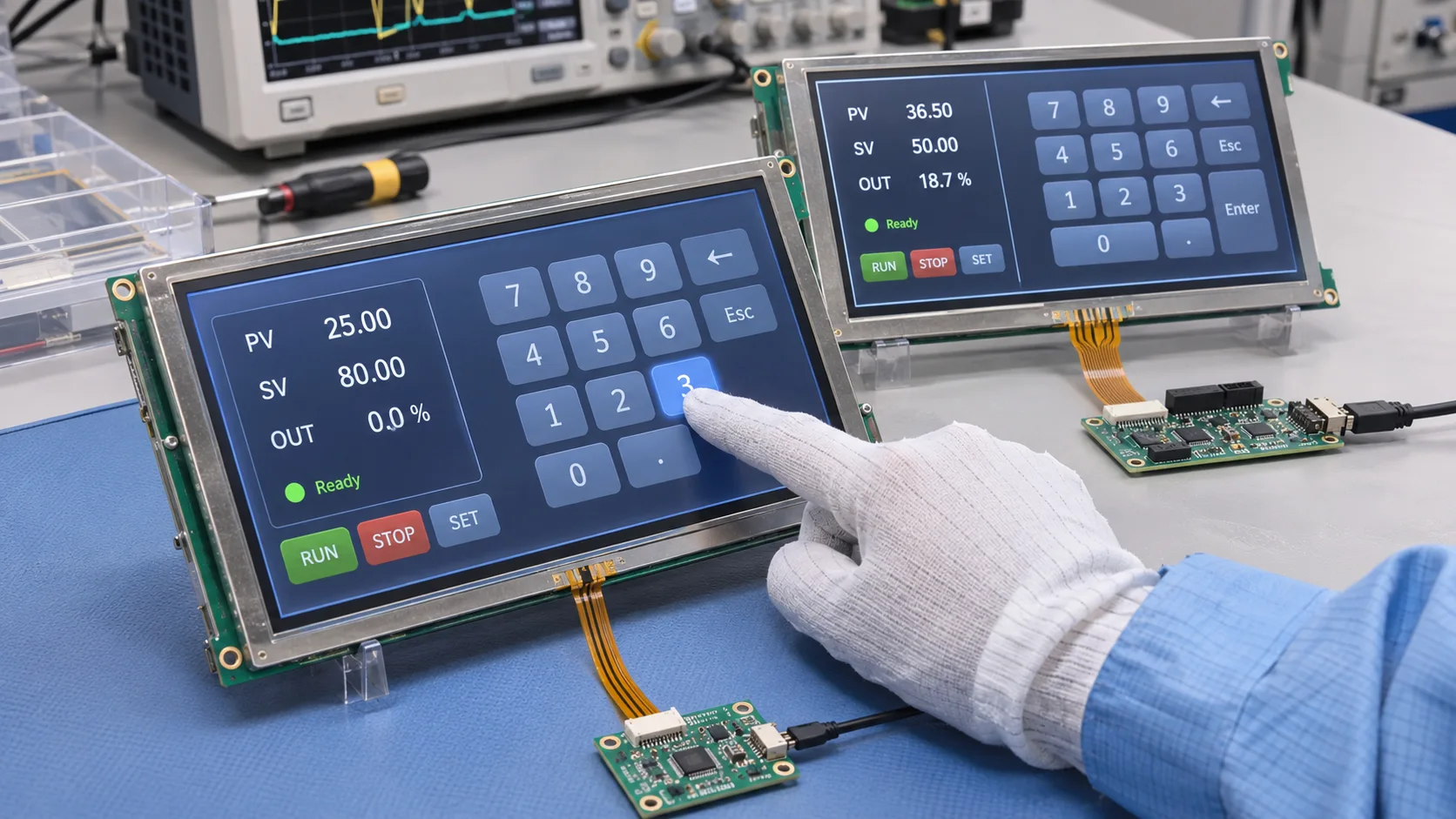
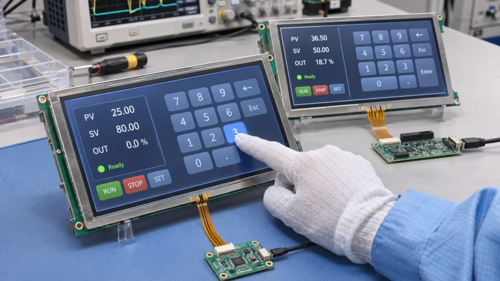
For instrument keypads, the choice between 4-wire and 5-wire resistive touch should start with repeated-use requirements and controller compatibility. A 4-wire panel can be a practical option when its tested durability meets the application. A 5-wire panel deserves consideration when operators repeatedly press the same virtual keys and coordinate stability is a priority. Neither architecture removes the need for application testing.
Here, an instrument keypad means on-screen buttons displayed beneath a resistive touch panel. Engineering and procurement teams should evaluate the sensor, controller, mounting arrangement, and software mapping together before approving a component for production.
What Changes Between 4-Wire and 5-Wire Resistive Touch?
Both architectures detect pressure that brings separated conductive surfaces into contact. The controller measures electrical signals and converts them into touch coordinates. The important distinction is how the layers participate in position measurement.
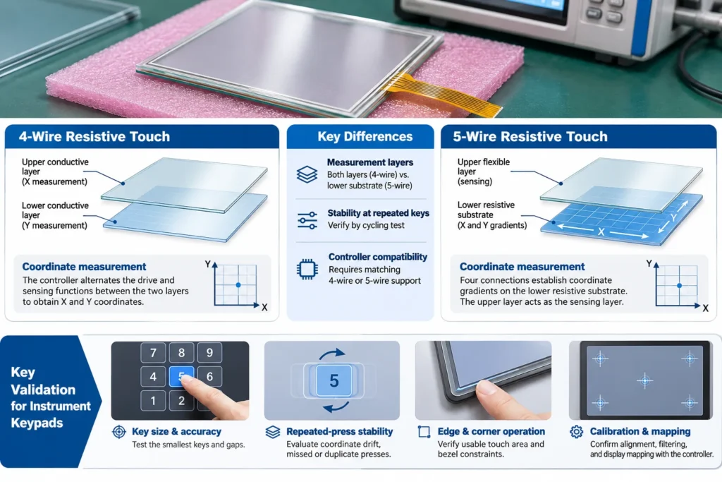
In a conventional 4-wire resistive touch screen, each conductive layer has two connections. The controller alternates the drive and sensing functions between the layers to determine the two coordinate axes. The electrical uniformity of both layers therefore matters to position accuracy.
In a conventional 5-wire resistive touch screen, four connections establish coordinate gradients on the lower resistive substrate. The flexible upper layer provides the sensing connection. Both coordinate measurements depend on the lower substrate’s resistive characteristics.
This arrangement can reduce the influence of changes in the flexible layer’s resistance on coordinate measurement. It does not make the upper surface immune to wear or physical damage. Contact quality, film condition, and the complete sensor construction still affect operation.
For buyers, the useful question is whether the proposed architecture offers a measurable advantage under the instrument’s actual input pattern.
Compare the Requirements That Affect Keypad Selection
| Procurement consideration | 4-wire panel | 5-wire panel |
| Coordinate measurement | Uses both conductive layers | Establishes coordinate gradients on the lower substrate |
| Repeated input at fixed keys | Verify stability after representative cycling | Evaluate whether the architecture improves stability under the same test |
| Controller selection | Requires compatible 4-wire support | Requires compatible 5-wire support |
| Mechanical integration | Confirm active area, border, tail, and mounting requirements | Confirm the same details for the proposed construction |
| Purchasing decision | Compare validated performance and total integration cost | Compare validated performance and total integration cost |
Avoid approving a panel from a generic touch-life figure alone. Two ratings may use different forces, contact tips, test locations, and acceptance criteria. Request those conditions before treating the figures as comparable.
A higher component quotation may be justified if testing demonstrates a relevant benefit. Conversely, an architecture change brings little value when the existing option already meets the documented requirement.
Define the Repeated-Press Pattern Before Requesting Samples
Instrument keypads often concentrate input on a few locations: numeric entries, confirmation keys, or frequently selected functions. A general tapping test spread across the surface may underrepresent that pattern.
Provide the supplier with the proposed keypad layout and identify the busiest regions. Include expected operating frequency, input method, and whether users hold or slide a finger across the surface.
Define acceptance in terms of the intended task. For example, the reported position should remain within an agreed tolerance relative to each key’s usable area. The test should also identify missed presses, duplicate events, and unintended selection of adjacent keys.
Evaluate initial behavior and behavior after the agreed cycling sequence. Keep the controller settings and mechanical arrangement consistent between candidates. Otherwise, a difference attributed to wire count may actually come from filtering, mounting pressure, or calibration.
Match the Controller and Cable Before Comparing Quotations
A 5-wire sensor is not a drop-in replacement for a 4-wire sensor simply because the outline dimensions match. The controller must support the architecture, and its connection scheme must match the panel.
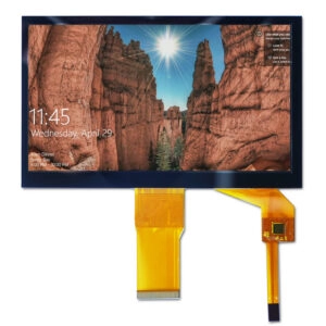
Request a pinout drawing that identifies each electrode connection, connector orientation, contact side, pitch, and tail exit direction. Confirm whether the quotation includes a bare sensor, a controller, or a touch-display module.
Separate the display interface from the touch interface. An RGB connection describes the display signal path; it does not establish how touch coordinates reach the host.
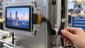
Cable routing also belongs in the comparison. Confirm available space, permitted bending, connector retention, and the route relative to potential electrical interference. A longer cable or changed routing arrangement should be evaluated with the intended controller.
Freeze the approved sensor, controller configuration, and cable drawing together. Substituting one item later may require renewed validation even when the purchase description still says “resistive touch.”
Validate Key Size, Calibration, and Edge Operation
Wire count alone does not determine whether an operator can select small virtual keys reliably. Sensor linearity, calibration, coordinate filtering, display alignment, and input technique all contribute.
Test the smallest keys and the narrowest gaps in the proposed interface. Include corners and edges, where usable touch area and bezel geometry may constrain operation. A successful demonstration at the screen center leaves these conditions untested.
Calibration should use the final display orientation and the intended mapping between touch coordinates and pixels. Check behavior after power cycling and after any software changes that affect scaling or rotation.
Define how a key becomes active: on initial contact, after a dwell period, or on release. Check how repeated presses and held contacts are interpreted. These software decisions affect keypad behavior but should not be presented as properties guaranteed by either sensor architecture.
Check Gloves and the Installed Mechanical Stack
Both architectures can support pressure-based input with suitable gloves or styluses. The actual activation force and response depend on the selected construction and operating conditions.
Use the intended gloves, including representative thicknesses, and specify the stylus tip when applicable. Compare deliberate presses, light presses, repeated entries, and release behavior. Avoid assuming that every nonconductive object is an acceptable input tool.
Test the installed arrangement as well as the loose sample. Bezel overlap, adhesive placement, gasket compression, and enclosure tolerances can change how the flexible surface moves.
Any protective layer must be compatible with the sensor’s operating principle. Request review of the proposed stack before adding material over the active surface. Optical readability and touch activation should be accepted together under the specified viewing and environmental conditions.
Build an RFQ Around a Controlled Component Specification
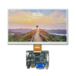
Miqidisplay lists resistive touch screen components and a 7-inch resistive touch display module. For an instrument project, confirm the exact sensor architecture and current specification for the proposed configuration before treating a product listing as an approved design.
The RFQ should distinguish mandatory requirements from preferences:
- Display diagonal, resolution, active area, and outline limits.
- Required touch architecture and controller scope.
- Connector details, cable routing, and mechanical drawings.
- Key layout, input tools, operating conditions, and acceptance tests.
- Sample quantity, forecast quantity, and documentation requirements.
Where the standard arrangement does not fit, discuss display component customization options against the drawing. Establish which changes require new samples and how approved revisions will be identified.
Retain the accepted specification, test conditions, and sample configuration as the purchasing reference. This gives incoming inspection and future orders a common basis.
Conclusion
Choose 4-wire resistive touch when the proposed panel and controller meet the instrument keypad’s documented requirements. Consider 5-wire when its measurement architecture addresses a demonstrated need for stability under concentrated repeated input.
Approve the complete configuration through representative testing. The sourcing decision should rest on compatibility, usable key accuracy, mechanical fit, and documented evidence.
FAQs
Is 5-wire resistive touch automatically more accurate?
No. Accuracy depends on the panel, controller, calibration, and installation. Compare measured results against the keypad’s requirements.
Can both types work with gloves?
Both can support suitable pressure-based glove input. Test the actual glove and selected panel because activation requirements vary.
Can a 4-wire controller operate a 5-wire panel?
Only if the controller explicitly supports that architecture and the required connections. Confirm its specification and pinout.
Does an LCD module’s resolution determine touch accuracy?
No. Display resolution and touch-coordinate performance are separate characteristics. Their mapping must be validated together.
Request a Technical Fit Review for Your Instrument Keypad
For a qualified instrument project, request a Miqidisplay technical fit review. Send the display type, size, dimensions, active area, resolution, interface, touch requirement, brightness, viewing direction, operating temperature, mechanical constraints, quantity, drawings, and integration environment. Include the keypad layout and repeated-press requirements so the proposed component fit, customization scope, sample requirements, documentation, and batch-consistency criteria can be assessed.
Email: mary@miqidisplay.com
WhatsApp: +86 189 6801 5464