







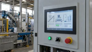
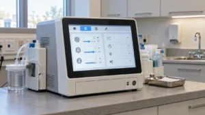

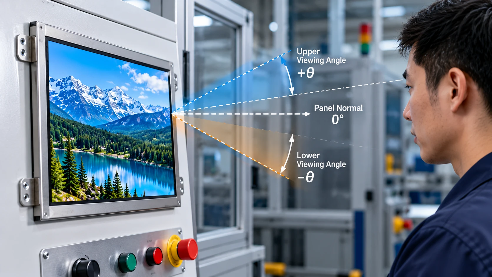
When a piece of equipment is installed at a known height and operators approach it from a repeatable position, TFT LCD viewing direction becomes a specification issue—not a last-minute panel preference. The buyer should define the intended eye position, allowable movement, contrast and color limits, and the panel’s physical orientation before requesting quotations. This prevents a screen that is electrically compatible but difficult to read once installed.
For a fixed-angle application, match the LCD module’s usable viewing cone to the equipment’s real line of sight. Document the normal viewing axis, upper and lower limits, side access, lighting, and the information that must remain legible. A supplier can then compare panels, confirm the data-sheet view direction, and identify whether a sample is needed.
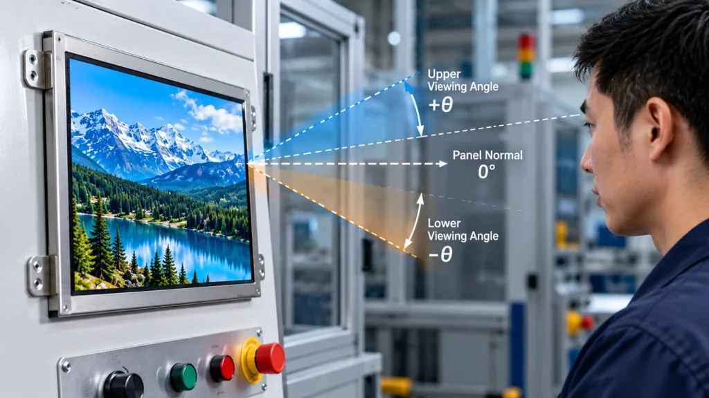
What “viewing direction” means on a TFT LCD
Viewing direction describes the direction from which a panel is intended to be observed. A data sheet may express performance as angles from the normal axis—for example, left/right/up/down values. “IPS” or “TN” identifies a panel family; it does not by itself confirm the usable angle, contrast retention, or color behavior required by an enclosure.
For procurement, separate three questions:
- Is the operator looking close to the panel normal, or from above, below, or the side?
- Must text remain readable only, or must colors and gray levels remain consistent?
- Is the display fixed in one orientation, or can the mounting angle change during installation?
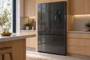
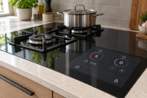
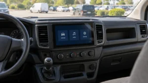
The answer should appear in the RFQ with a drawing or a simple coordinate description. A fixed-angle enclosure may tolerate a narrower cone when the operator position is controlled. A service access door, a high mounting position, or a panel viewed from a standing aisle can create a large vertical offset even when the equipment itself never moves.
Why fixed-angle equipment needs a deliberate angle choice
Viewing-angle figures are usually measured under defined test conditions. They do not describe every combination of backlight, ambient light, graphics, temperature, cover glass, and observer position. Contrast can fall before the published limit, and color or grayscale shifts may be more noticeable on an alarm screen than on a simple numeric readout.
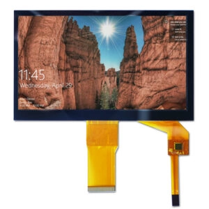
The mechanical design also changes the result. A deep bezel can block part of the viewing cone, while a protective window can add reflections. A tilted panel may improve the vertical line of sight but create glare from overhead lighting. If a touch layer, cover glass, or optical stack is added, check the final assembly rather than inferring performance from the bare panel.
Specify the viewing task instead of asking for a generic “wide viewing angle TFT.” State the normal eye point, permitted movement in degrees or millimeters, critical content, and site lighting.
TN, IPS, and the viewing task
Panel structure is a starting point, not the final decision. TN panels can be practical when the line of sight is controlled and the equipment values a repeatable orientation. IPS panels are often considered when observers stand at different lateral positions or image uniformity matters across a broader cone. Check the panel specification against the enclosure geometry and environment.
Consider the following trade-offs:
- Controlled operator position. A single operator in front of a panel may not need the same angular margin as a team reading it from a side aisle.
- Vertical offset. A panel above eye level can be more sensitive to an upward or downward view. Check the up/down values separately.
- Content sensitivity. Large numerals may remain usable after a contrast change, while color-coded status or fine curves may not.
- Batch consistency. If several positions use the same module, approve a sample in the most difficult position and freeze the viewing-direction requirement.
Build the specification around the equipment geometry
Before comparing panels, prepare a short viewing-direction brief:
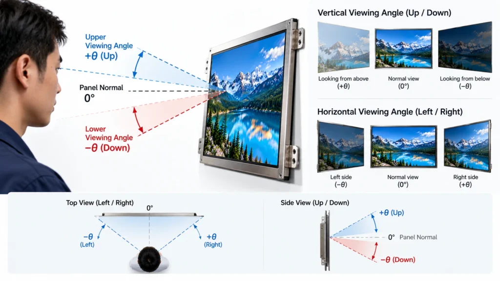
1. Draw the normal viewing axis
Show the panel plane, enclosure tilt, operator eye height, and distance. Mark the primary axis as zero degrees and add the maximum left/right and up/down deviation. A supplier can then interpret the panel’s angle convention correctly.
2. Define the readability threshold
Write down whether acceptance means readable characters, preserved contrast, stable color identification, or a measured luminance/contrast threshold. Avoid “good from the side”; match the threshold to the equipment’s risk and the operator’s decision.
3. Record the optical and mechanical stack
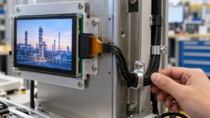
Include cover glass, touch requirement, anti-glare treatment, gasket or bezel depth, mounting direction, and any air gap. These parts can change reflections and the apparent viewing cone. For an existing cutout, provide outline dimensions and active area, not only diagonal size.
4. Check environmental conditions
Temperature, sunlight, dust, vibration, and condensation can affect the result. A panel with a defined operating-temperature range may be more appropriate than a similar module that has not been checked for the installation environment. Verify every limit against the current product specification.
Supplier and sample checks for fixed-angle LCD modules
Ask the supplier to return the viewing-direction information in the same format as the RFQ. Useful questions include:
- Which panel orientation is the reference for the stated left/right/up/down angles?
- Are the values typical or guaranteed limits, and which test condition applies?
- What changes when a cover glass or touch layer is added?
- Can the supplier provide a mechanical drawing, interface definition, and optical-stack description for review?
- Which sample configuration matches the proposed production module?
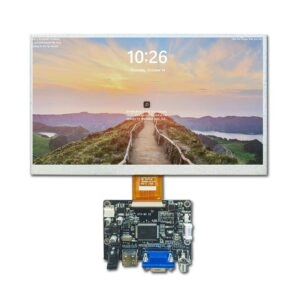
Miqidisplay’s product pages illustrate why this level of detail matters. Its 19-inch AUO TN LCD panel for industrial integration lists 1280×1024 resolution, 350 cd/m² brightness, LVDS interface, a -30°C to 85°C operating range, and a TN view-direction designation. Its 18.5-inch AUO IPS LCD module lists 1920×1080 resolution, 500 cd/m² brightness, eDP interface, and an IPS view-direction designation. These are starting points for fit review, not substitutes for checking the final installation geometry.
When a standard panel is close but not exact, document the gap instead of changing the requirement informally. Miqidisplay describes custom display solutions for cable, interface, PCB, mounting, and cover-glass adjustments. Request confirmation of the proposed configuration and sample evidence.
RFQ checklist for a viewing-direction decision
Include these fields in the sourcing package:
- Display type and panel structure under consideration
- Diagonal size, outline dimensions, active area, and resolution
- Normal viewing axis plus required left/right/up/down limits
- Readability, contrast, color, or grayscale acceptance criteria
- Interface, power conditions, cable exit, and connector constraints
- Brightness, surface treatment, cover glass, and touch requirement
- Operating and storage temperature, ambient light, vibration, and moisture exposure
- Quantity, forecast, drawings, sample plan, and change-control expectations
This checklist lets engineering and procurement compare like-for-like offers. It also reduces the risk of approving a module based on a headline “wide angle” label while overlooking a vertical limitation, reflected glare, or a changed optical stack.
Conclusion
For equipment installed at a fixed angle, TFT LCD viewing direction should be specified as an installation geometry and acceptance requirement. Start with the operator eye point, distinguish readability from color or contrast stability, and document the complete optical and mechanical stack. Then compare the panel’s view-direction data with a sample installed in the most demanding position. A controlled specification makes supplier quotations clearer and protects repeat production from silent changes.
FAQs
Is viewing direction the same as viewing angle?
No. Viewing direction describes the intended orientation, while viewing-angle data describes how far an observer can move from the normal axis under stated test conditions.
Should vertical and horizontal angles be specified separately?
Yes. A high or low mounting position can create a different limitation from a side-view requirement, so record both axes.
Is a sample necessary when the equipment angle is fixed?
Usually it is prudent when content, glare, cover glass, or multiple operator positions are important. Approve the sample in the most difficult real position.
What should be sent for a technical fit review?
Send the display type, size, dimensions, active area, resolution, interface, brightness, viewing direction, temperature, mechanical constraints, quantity, drawings, and integration environment.
Request a TFT LCD Viewing-Direction Fit Review
Send Miqidisplay your display type, diagonal size, outline dimensions, active area, resolution, interface, brightness, required viewing direction, operating temperature, mechanical constraints, quantity, drawings, and installation environment. This information enables the engineering team to assess panel compatibility, viewing-angle requirements, customization scope, sample needs, and documentation for repeat production. Submit your TFT LCD sourcing requirements to Miqidisplay for a technical fit review.
Email: mary@miqidisplay.com
WhatsApp: +86 189 6801 5464