





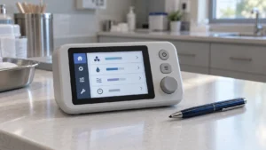
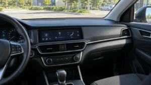
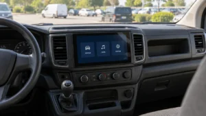
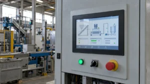
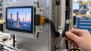
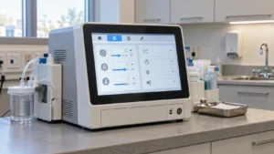

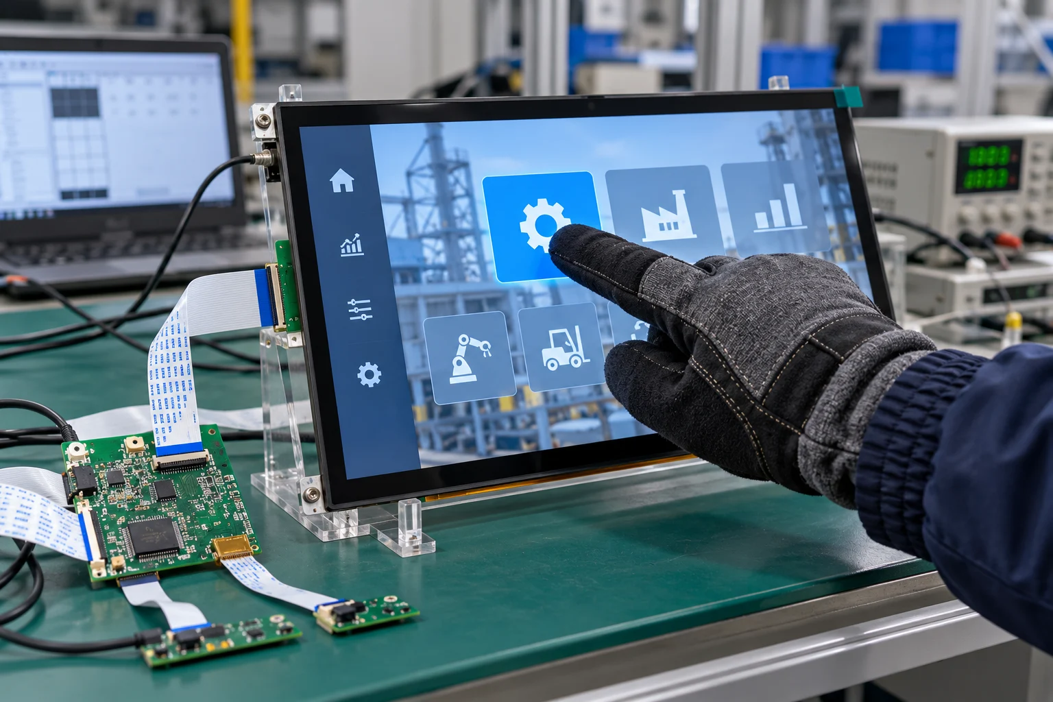
For operators wearing insulated, coated, or layered work gloves, a standard capacitive touch panel may miss touches or respond inconsistently. Specify glove operation as a complete touch-stack and validation requirement—not as a promise attached to a panel name. Buyers should define glove construction, touch location, response target, cover-lens stack, controller interface, and environmental conditions before requesting samples.
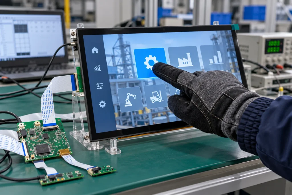
Why Thick Gloves Challenge Capacitive Sensing
Projected-capacitive sensing detects a change in an electric field. A bare finger couples readily to the sensor, while a thick glove adds distance and dielectric material between the operator and the sensing electrodes. Some gloves also contain coatings, seams, moisture, or conductive fibers that change the signal in different areas of the hand.
“Glove compatible” is not a universal operating class. Thin textile, coated, and insulated gloves can produce different results on the same panel. A supplier should ask for the actual glove or a representative sample, not only a nominal thickness. Identify whether the operator uses a fingertip, knuckle, palm, or stylus-like tool.
Specify the Complete Touch Stack
Start With Sensor, Cover Lens, and Bonding
Glove operation is affected by the distance from the outer surface to the sensor, the cover-lens material, adhesive layers, printed borders, and any air gaps. A thicker cover or larger gap can reduce signal margin, while an unsuitable coating may alter surface friction or optical performance. For a procurement specification, define the active area, outline dimensions, cover-lens thickness range, surface finish, border artwork, and whether optical bonding is required. Ask the supplier to identify which values are fixed and which can vary between samples and production lots.
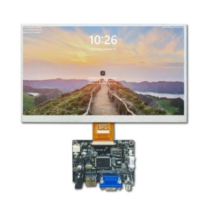
Miqidisplay’s 8-inch capacitive module is a useful reference for this type of specification: its published configuration lists a 1024×768 LCD, LVDS interface, 1000 cd/m² brightness, capacitive touch support, and a -30°C to 80°C operating range. Those facts describe that particular module; they do not prove thick-glove performance. Glove response must be verified on the final stack.
Treat Controller Tuning as Part of the Design
The touch controller, firmware parameters, scan strategy, and noise environment influence whether a weak glove signal is recognized. Increasing sensitivity alone can create false touches, unstable edges, or poor water rejection. Ask for a documented tuning process that covers threshold, debounce, noise filtering, palm rejection, and wake behavior where relevant. The supplier should explain which parameters are configurable and how a locked configuration will be identified in the approved sample and production records.
Define the Glove Requirement as a Test Condition
Replace “works with winter gloves” with a measurable test matrix. Include:
- Glove identification: brand or internal part number, material, coating, nominal thickness, size, and whether the glove is dry, damp, or contaminated during testing.
- Touch action: single tap, repeated tap, swipe, drag, edge touch, and multi-point action if the application needs it.
- Touch zones: center, corners, narrow keys, icon edges, and any area near the printed bezel.
- Operating state: display powered from the intended host electronics, with the final cable, enclosure, grounding, and nearby electrical loads.
- Acceptance criteria: recognition rate, maximum response time, missed-touch limit, false-touch limit, and recovery after the glove leaves the surface.
Test at expected temperatures, humidity, and viewing angles. If operators will change glove types, test the worst-case combination. Record the panel revision, controller firmware, cable, and cover-lens configuration with every result.
Match the Display Module to the Equipment
Glove support cannot compensate for a display module that is difficult to integrate. Confirm diagonal size, active area, outline, mounting points, thickness, connector location, viewing direction, brightness, resolution, and operating temperature before choosing the touch panel. For many industrial interfaces, a 7-19 inch range provides workable space for gloved targets while remaining practical for embedded equipment; the appropriate size remains application-dependent.
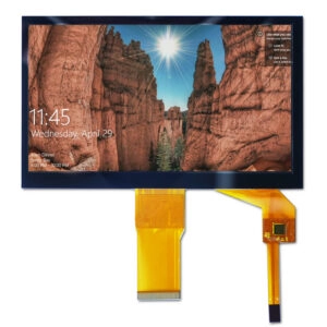
Miqidisplay lists 7-inch, 8-inch, 10.4-inch, 11.6-inch, 13.3-inch, 14.9-inch, 15.6-inch, and 17.3-inch touch-related options in its product range. The 11.6-inch G+G capacitive touch panel is listed with an IIC interface, while larger 17.3-inch panels are listed with USB or IIC variants. These are starting points for a fit review, not a guarantee that every configuration supports a particular glove.
When a project needs a compact screen, compare the touch target size with the glove’s usable fingertip area. A high pixel count does not automatically make controls easier to operate. The user interface should provide sufficiently large targets, spacing, and confirmation feedback, while the panel specification should preserve the required active area and bezel layout.
Control Mechanical and Electrical Integration Risks
The enclosure can reduce touch margin if it presses on the bezel, leaves an uncontrolled air gap, or introduces a conductive frame close to the sensing area. Define the mounting stack-up, compression limits, gasket position, grounding path, and cable routing. Keep approved cover lens, adhesive, spacer, and bracket revisions linked to the display-module part number.
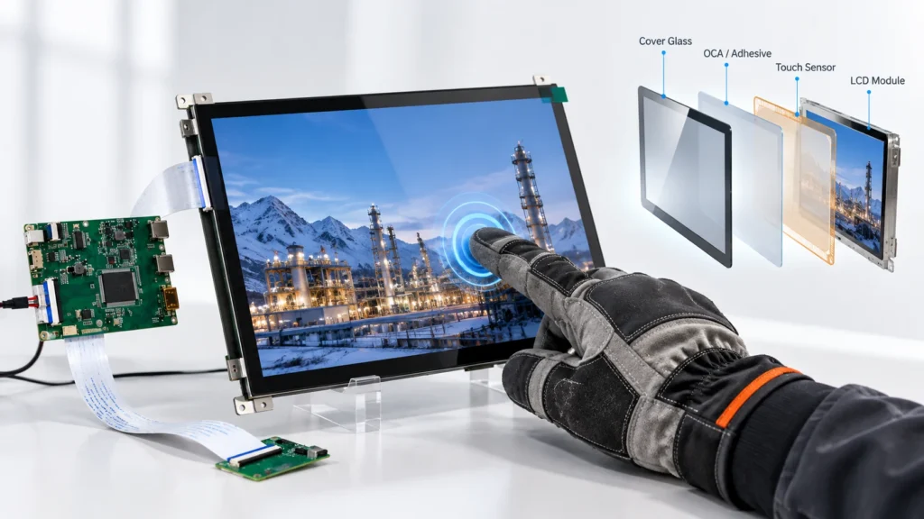
On the electrical side, document the touch interface—such as IIC or USB where offered—along with voltage, connector pinout, cable length, shielding, and host controller requirements. Noise from power converters, motors, radios, or long unshielded cables may change results. A supplier should review the complete integration environment and state which tests must be repeated after a cable, bezel, or firmware change.
Build an RFQ That Supports Supplier Comparison
An effective RFQ asks suppliers to respond to the same evidence package. Include the glove test matrix, display size, active area, resolution, interface, brightness, viewing direction, operating temperature, mechanical constraints, target quantity, drawings, and integration environment. Request a sample configuration, dimensional drawing, electrical specification, touch-controller identification, revision-control method, and proposed validation procedure.
During sample approval, compare suppliers under identical fixtures and host electronics. Check the center and edge zones, repeated inputs, gloved swipes, moisture conditions, and cold-start behavior when relevant. Ask how the approved sample will be tied to the production bill of materials and how deviations will be communicated. This reduces the risk that a later cover, cable, or controller substitution changes glove performance without a visible change in the product name. If the project needs coordinated changes to glass, cable, or touch electronics, review Miqidisplay’s customization solutions as part of the sourcing discussion.
For projects that need a defined customization path, review Miqidisplay’s capacitive touch screen category and compare the published size, interface, temperature, and brightness fields with the RFQ. A project-specific fit review is still required before any performance claim is accepted.
Conclusion
Supporting thick gloves with a capacitive touch panel is a system specification task. Define the actual glove, control the sensor-to-surface stack, tune and document the controller, and validate the final panel inside the intended enclosure and electrical environment. Use a 7-19 inch module when it fits the operator workflow, but approve the exact size and configuration through evidence rather than a generic compatibility label.
FAQs
Can Any Capacitive Touch Panel Support Thick Gloves?
No. Response depends on glove material and thickness, touch-stack geometry, controller tuning, noise, and enclosure design. Approval should be based on tests with the actual glove and final module configuration.
Is Higher Touch Sensitivity Enough?
Not necessarily. More sensitivity can increase false touches or water-related errors. Thresholds, filtering, grounding, and mechanical stack-up must be tuned together.
Should Glove Testing Use the Production Enclosure?
Yes. The bezel, gasket, grounding, cable routing, host electronics, and nearby noise sources can change capacitive performance. A loose bench test is useful for screening but not final approval.
What Size Display Is Practical for Gloved Operation?
The answer depends on target size, viewing distance, enclosure space, and the number of controls. Miqidisplay lists several touch-related modules from 7 to 17.3 inches; the final selection should be confirmed against the project drawing and test matrix.
Request a Miqidisplay Technical Fit Review
Send Miqidisplay the display type, diagonal size, outline dimensions, active area, resolution, interface, touch requirement, brightness, viewing direction, operating temperature, mechanical constraints, quantity, drawings, glove samples or specifications, and integration environment. These inputs allow the technical team to assess a compatible screen or display-module configuration, customization scope, sample requirements, documentation needs, and batch-control checkpoints. Request a Miqidisplay technical fit review before freezing the RFQ or approving a production sample.
Email: mary@miqidisplay.com
WhatsApp: +86 189 6801 5464