





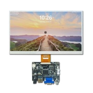
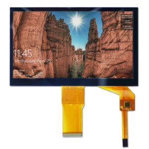

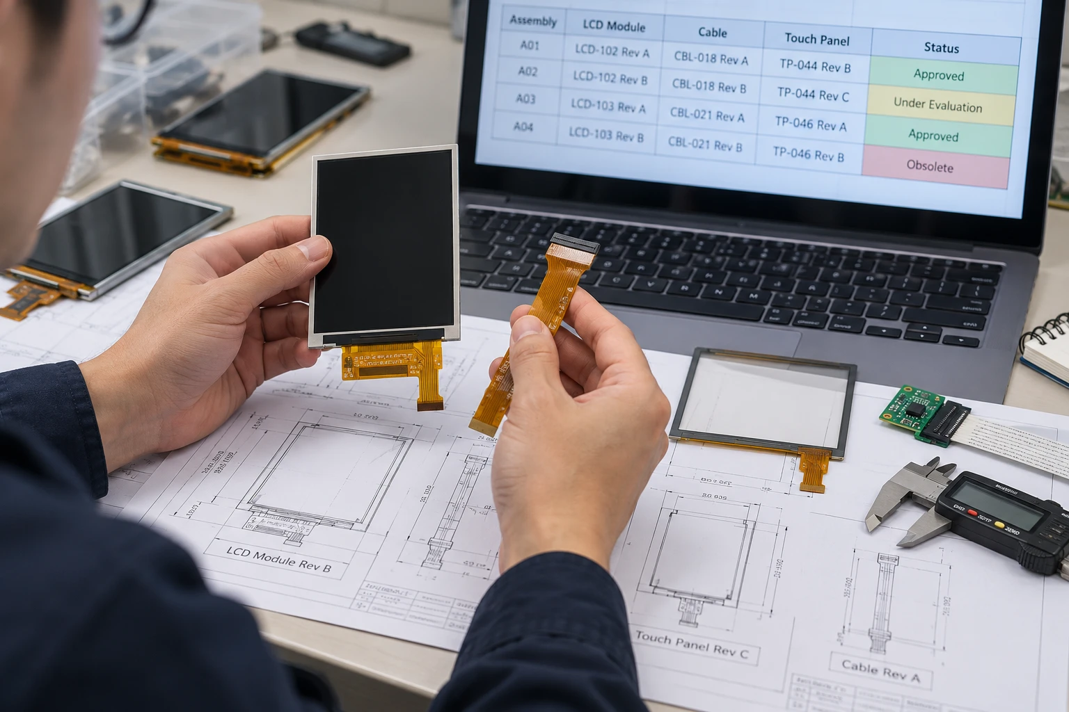
When an OEM display assembly changes, the LCD module, cable, and touch layer must be controlled as one coordinated configuration. Updating only one drawing or purchase record can create incompatible parts, unclear test results, and mixed versions in production.
A reliable revision process connects the electrical, mechanical, optical, and touch-related records for every approved assembly. The objective is not simply to assign new revision letters. It is to make sure that engineering, procurement, manufacturing, quality, and the display supplier are all working from the same technical baseline.
Start With One Assembly-Level Revision Baseline
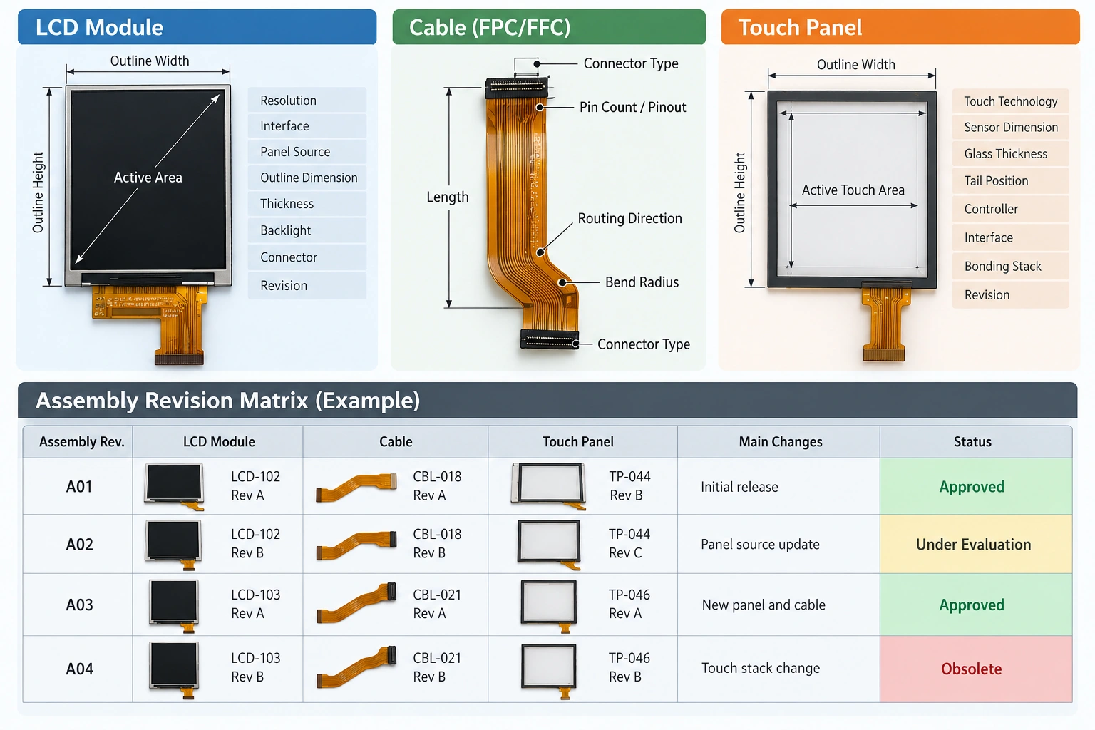
Treat the LCD module, cable, and touch component as a linked assembly rather than three independent items. Create a master configuration record that identifies:
- LCD module part number and revision
- Active area, outline dimensions, thickness, and mounting features
- Resolution and display interface
- Cable part number, length, pin count, pinout, connector type, and routing
- Touch technology, sensor dimensions, tail location, and controller interface
- Cover or bonding requirements, where applicable
- Approved drawings, datasheets, samples, and test records
The assembly-level record should also state which component revisions were tested together. A new cable may fit the connector but still alter signal integrity, bend radius, or mechanical clearance. A new touch tail may use a different pin assignment even when the visible touch area remains unchanged.
A practical rule is that the assembly revision should change whenever a component change can affect fit, function, performance, reliability, or verification results.
Define What Counts as a Revision
Not every editorial correction requires a new product revision. However, teams should agree in advance which changes trigger formal control.
An LCD module revision normally requires review when it changes the panel source, active area, outline, thickness, connector, interface, resolution, optical stack, backlight arrangement, or environmental specification.
A cable revision normally requires review when it changes length, conductor arrangement, pin assignment, connector, shielding, bend direction, exit position, or insulation construction.
A touch revision normally requires review when it changes sensor geometry, glass thickness, tail position, controller, interface, touch technology, bonding stack, or active touch area.
A drawing correction that does not change the physical or functional item may be recorded as a document revision instead. The change description should make this distinction explicit so procurement does not treat a document-only update as a new component, or overlook a real hardware change.
Use a Cross-Reference Matrix
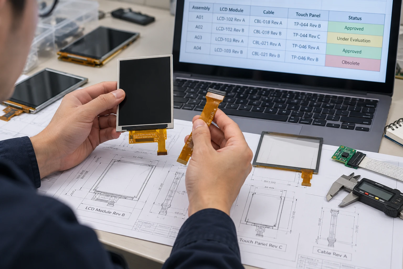
A cross-reference matrix is the simplest way to prevent partial updates. Each row represents an approved assembly configuration, while the columns identify the exact component and document versions.
| Assembly baseline | LCD module | Cable | Touch layer | Key verification |
| A01 | LCD-102 Rev B | CBL-018 Rev A | TP-044 Rev C | Fit, interface, touch response |
| A02 | LCD-102 Rev C | CBL-018 Rev B | TP-044 Rev C | Optical and electrical recheck |
| A03 | LCD-103 Rev A | CBL-021 Rev A | TP-046 Rev A | Full integration validation |
The matrix should identify whether a combination is approved, under evaluation, obsolete, or prohibited. It should also record the sample identity used for testing. This prevents a test report from being associated with a part number that looks correct but contains a different cable or touch tail.
For a deeper procurement-level explanation of formal notices and lifecycle records, see the LCD module lifecycle and change-notice guide.
Coordinate Electrical and Mechanical Interfaces
Revision coordination becomes critical at the interfaces between the parts.
For the LCD module and cable, compare the connector family, pin numbering, signal assignment, power pins, grounding, cable length, and routing direction. A connector that appears identical may have a different keying, contact arrangement, or pin definition. The cable drawing should reference the module drawing directly instead of relying on a generic connector description.
For the cable and touch layer, review tail position, fold direction, bend radius, adhesive zones, and clearance from the enclosure. A longer cable can create excess slack, while a shorter one can apply stress to the connector or bonded tail. A changed exit position may also interfere with brackets or shielding.
For the LCD module and touch layer, compare active area, viewing window, stack-up thickness, mounting datum, and bonding dimensions. A touch sensor can be electrically compatible while still producing a visible border mismatch or mechanical interference.
When the interface, pinout, or power requirement changes, update the assembly drawing and the integration test plan together. The TFT LCD datasheet review guide provides a useful document-checking reference for this stage.
Build a Change Package, Not Just a New Drawing
A controlled revision should be released as a complete change package. At minimum, include:
- Change description and reason
- Old and new part numbers or revisions
- Marked-up drawings showing affected dimensions or interfaces
- Updated datasheets and pinout information
- Compatibility statement for unchanged components
- Sample identification and labeling method
- Required inspection or validation activities
- Effective date and transition instructions
- Disposition of existing inventory
- Approval signatures or electronic authorization
The change description should answer three questions: what changed, why it changed, and how the change was verified. “Updated cable” is not sufficient. A useful description might state that the cable exit position moved to clear an enclosure rib, the length changed, and fit was verified in the latest housing.
Keep superseded documents accessible but clearly marked as obsolete. Removing them entirely can make historical investigation difficult, while leaving them in an uncontrolled shared folder creates a risk that an old file will be reused.
Control Samples and Test Evidence
Every revision should be traceable to a physical sample or build lot. Label samples with the full assembly baseline, not only the LCD module number. A label such as “LCD-102 Rev C / CBL-018 Rev B / TP-044 Rev C” gives the test team enough information to reproduce the configuration.
The required verification depends on the change. A cable length change may require mechanical fit, connector retention, bend, and signal checks. A touch-layer change may require touch accuracy, edge performance, optical inspection, and bonding review. An LCD module change may require interface timing, brightness, viewing behavior, temperature exposure, and enclosure fit checks, depending on the application.
Do not assume that a successful test of one component proves the complete assembly. The purpose of configuration testing is to confirm the relationship between the parts.
Align Procurement and Production Timing
Engineering approval is only one part of revision control. Procurement must know when the new revision becomes effective, whether old stock may be consumed, and whether mixed versions are allowed.
Use a transition plan that identifies:
- Last approved shipment of the previous baseline
- First approved shipment of the new baseline
- Existing inventory affected by the change
- Required incoming inspection
- Packaging or labeling differences
- Sample quantity for first-article review
- Rules for preventing mixed kits
For long-running programs, require suppliers to notify the project team before changing the LCD module, cable, touch component, connector, or related documentation. Miqidisplay’s custom display solutions page confirms that cable length, position, pins, connectors, touch add-ons, and interface arrangements can be part of a customization discussion. The exact feasibility and verification requirements still depend on the project specification.
What to Send a Display Supplier
A supplier can coordinate revisions more effectively when the inquiry includes the complete integration context. For buyers reviewing touch-enabled module options, Miqidisplay’s Industrial Touch Panels category provides a relevant product range to reference before submitting the revision package. Provide:
- Display type and diagonal size
- Active area and outline dimensions
- Resolution and interface
- Cable length, exit direction, pinout, and connector requirements
- Touch requirement and active touch area
- Cover or bonding constraints
- Brightness and viewing direction
- Operating temperature
- Enclosure drawings and mechanical restrictions
- Quantity and expected production stage
- Existing samples, drawings, and revision history
- The environment in which the assembly will operate
For example, a 7-inch MIPI LCD module with in-cell touch has a defined resolution, interface, temperature range, brightness, and touch configuration on its product record. Such information is useful only when matched against the buyer’s complete mechanical and electrical requirements. The 7-inch MIPI in-cell touch LCD module can serve as a reference point for the type of coordinated data that should appear in a sourcing discussion.
Conclusion
LCD module, cable, and touch revisions should be managed as a single configuration problem. The key controls are an assembly-level baseline, a cross-reference matrix, interface review, complete change packages, traceable samples, and a controlled procurement transition.
This approach reduces ambiguity when a part number changes and makes it easier to determine exactly which combination was designed, tested, purchased, and released. It also gives the supplier enough information to assess compatibility before a change reaches production.
FAQs
Should every cable change create a new assembly revision?
Not automatically. If the cable change affects fit, routing, pinout, signal behavior, or strain, the assembly should receive a new revision. A document-only correction may be controlled separately when the physical item is unchanged.
Can the same LCD module revision use two cable revisions?
It can, but only when both combinations are explicitly approved and independently verified where necessary. Otherwise, procurement and production may create an uncontrolled mixed configuration.
What should be checked when the touch tail changes?
Review pin assignment, controller compatibility, tail position, fold direction, bend radius, bonding area, enclosure clearance, and touch performance. The visible sensor area alone does not prove compatibility.
How should old samples be handled?
Keep them identifiable and segregated as superseded or reference samples. Their revision identity should remain visible so historical test results are not confused with the current production baseline.
When should a supplier receive the full enclosure drawing?
Provide it whenever mechanical clearance, cable routing, mounting, touch alignment, or stack-up affects the revision decision. A component-only review may miss an enclosure-level conflict.
Request an LCD Module Revision Fit Review
For a coordinated revision review, contact the Miqidisplay technical team with the display type, diagonal size, active area, outline dimensions, resolution, interface, touch requirement, brightness, viewing direction, operating temperature, cable details, mechanical constraints, quantity, drawings, and integration environment. These inputs allow Miqidisplay to assess component compatibility, potential customization scope, sample requirements, and the documentation needed for a controlled LCD module, cable, and touch configuration.
Email: mary@miqidisplay.com
WhatsApp: +86 189 6801 5464