





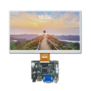
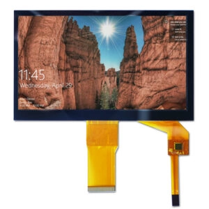






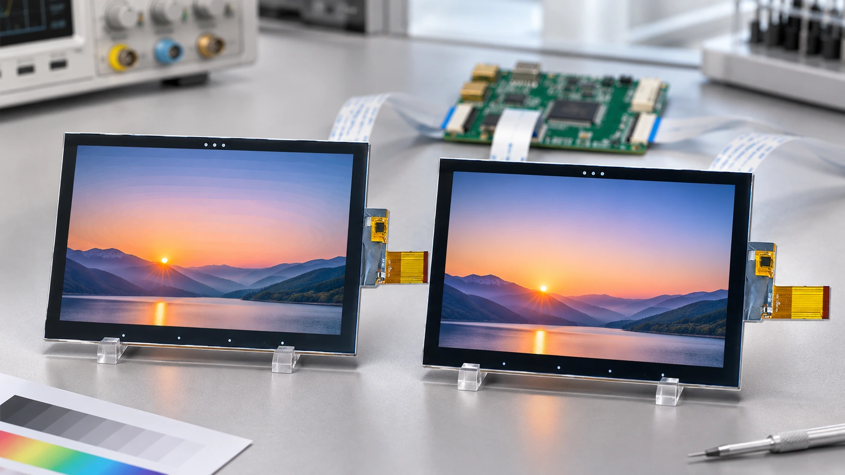
Choosing between 18-bit and 24-bit color for an OEM TFT LCD module starts with two questions: what visual detail must the application preserve, and what can the complete display path support? An 18-bit configuration may suit equipment showing text, icons, and solid status colors. A 24-bit configuration provides finer tonal steps for gradients, photographs, and detailed graphics. Approval should depend on documented compatibility and representative sample testing.
The purchasing risk is treating “24-bit color” as a complete specification. Host output, transmitted pixel format, controller processing, and native panel depth can differ. Define each one before comparing quotations.
What 18-Bit and 24-Bit Color Actually Mean
For RGB color, the total bit count describes the combined red, green, and blue values assigned to a pixel.
| Specification | 18-bit RGB | 24-bit RGB |
| Common format | RGB666 | RGB888 |
| Bits per color channel | 6 | 8 |
| Levels per channel | 64 | 256 |
| Possible RGB combinations | 262,144 | 16,777,216 |
| Main evaluation concern | Whether tonal steps remain acceptable | Whether the full path preserves finer steps |
These numbers describe encoding capacity. They do not establish color accuracy, gamut, contrast, viewing-angle stability, or brightness uniformity. A higher bit count cannot compensate for unsuitable optical characteristics.
Also distinguish bits per pixel from bits per channel. A supplier describing an “8-bit panel” may mean eight bits for each color channel, totaling 24 bits per RGB pixel. Ask for explicit terminology in the quotation and datasheet.
Separate Interface Format from Native Panel Depth
A module accepting RGB888 input does not necessarily reproduce every input value as a distinct native panel level. Its controller may reduce precision, apply dithering, or use another processing method before driving the panel.
Conversely, an application may generate a lower-precision framebuffer even when the downstream interface supports 24-bit transmission. The additional transmission capacity does not restore information already discarded upstream.
Request confirmation of four separate fields:
- Application framebuffer format.
- Host-controller output format.
- Module input format and configuration.
- Native panel depth and any dithering or frame rate control.
Frame rate control creates intermediate perceived shades by changing output across frames. Spatial dithering distributes differences between neighboring pixels. Either approach can influence appearance, so evaluate the actual implementation rather than assuming equivalence to native eight-bit channels.
For purchasing records, replace a vague “16.7 million colors” requirement with a statement identifying accepted input formats, native depth, processing behavior, and required operating mode.
Decide Whether the Content Needs Finer Tonal Steps
An interface containing large text, simple diagrams, and clearly separated status colors may show little practical benefit from additional tonal levels. The important question is whether users can distinguish the information reliably under installed conditions.
Gradients, shaded technical illustrations, photographs, and subtle background transitions deserve closer review. Reducing precision can create visible bands where the source image contains a smooth progression.
Test the content that will ship. A colorful demonstration image can conceal weaknesses that become obvious on a large gray gradient or a dark application background.
Include near-black transitions, neutral grays, saturated colors, and the smallest meaningful differences in the application. Evaluate them at the intended viewing distance and brightness. If color communicates a critical state, assess its distinguishability separately from the module’s headline color count.
Check the Electrical Implementation Before Comparing Cost
On a parallel RGB interface, RGB666 commonly uses six data signals per channel, while RGB888 uses eight. Synchronization, clock, enable, power, and ground connections are additional requirements.
That difference can affect host pin availability, connector allocation, and routing. However, it does not mean every 18-bit module has a lower total connector pin count than every 24-bit module.
Serial interfaces require a different analysis. For MIPI DSI, RGB666 may use packed or loosely packed transmission; the latter can occupy a 24-bit transport allocation. Therefore, changing the nominal color format does not automatically reduce link bandwidth.
For LVDS, confirm the supported bit depth, channel arrangement, data mapping, and configuration settings. A matching connector does not prove that the host and module assign color bits identically.
Where serial-link capacity is a constraint, the complementary MIPI DSI lane-count and bandwidth guide helps organize the separate timing and transport checks.
Calculate Memory and Data Traffic Separately
Color depth affects storage only when the software actually uses the corresponding memory layout. A framebuffer may allocate 24 or 32 bits per pixel even when the panel receives 18-bit color.
For tightly packed image data:
Frame storage = horizontal pixels × vertical pixels × bits per pixel ÷ 8
An illustrative 800 × 480 frame requires 864,000 bytes at 18 bits per pixel and 1,152,000 bytes at 24 bits per pixel. Actual allocation may be higher because of stride alignment, padding, buffering, or graphics-library requirements.
Do not use those storage figures as a complete interface-bandwidth estimate. Continuous transmission can include blanking and protocol overhead, while command-based updates may transfer selected regions.
Similarly, do not assume that 18-bit operation guarantees lower module power. Backlight settings, panel electronics, host processing, and interface activity all contribute. Request measurements under comparable operating conditions if energy use affects the purchasing decision.
Approve Samples with a Controlled Visual Test
Compare candidate modules using the same source files, host configuration, brightness target, and viewing conditions. Otherwise, differences attributed to color depth may come from unrelated settings.
Use a repeatable approval sequence:
- Confirm the transmitted format and module initialization settings.
- Display grayscale ramps and individual red, green, and blue ramps.
- Check application gradients, photographs, icons, and thin graphic elements.
- Observe static images and moving transitions for objectionable artifacts.
- Repeat relevant checks across the intended brightness and temperature conditions.
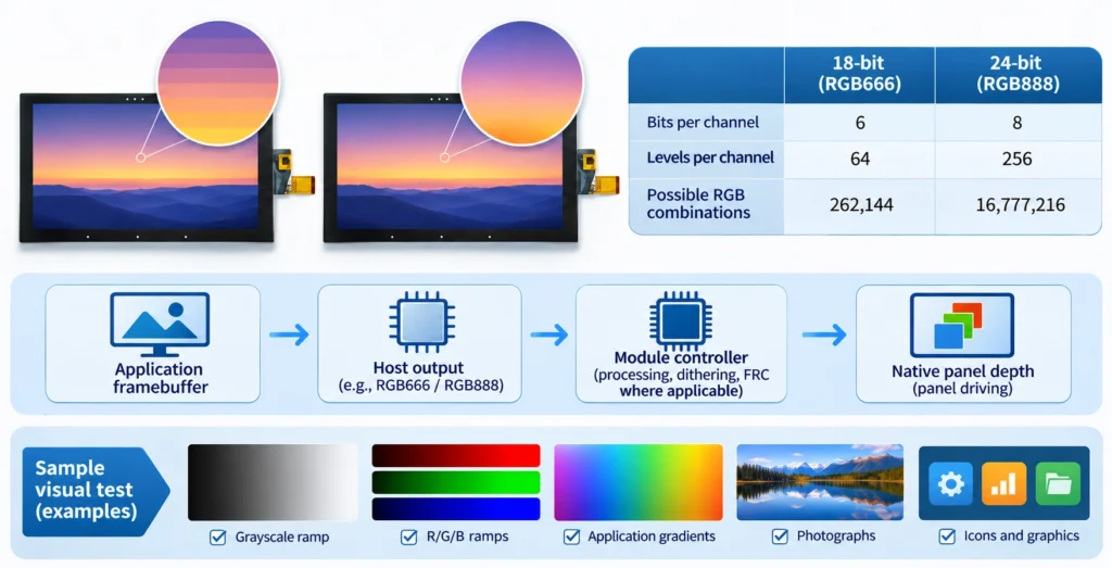
Keep the source images and configuration with the sample record. Record panel revision, controller settings, cable identification, and acceptance decisions.
A photograph is useful documentation but should not replace direct inspection. Camera processing, exposure, and image compression can hide banding or introduce artifacts absent from the panel itself.
Turn the Comparison into an RFQ Requirement
Screen candidates from Miqidisplay’s TFT LCD display module range against the required optical, electrical, and mechanical characteristics before selecting a color-depth configuration.
For example, its 8-inch MIPI LCD module with capacitive touch provides a starting point for an 800 × 1280 integration project. The supported pixel formats, native depth, and processing behavior still require confirmation for the exact proposed revision.
Ask suppliers to state whether both formats are supported on the same part number, whether a configuration change is required, and whether changing formats affects timing or initialization.
Attach the representative test images and describe unacceptable results. “No objectionable banding on the approved application gradient under agreed test conditions” is more actionable than “excellent color.”
Keep touch requirements separate: touch-point count and touch-interface type do not establish display color depth.
Conclusion
For OEM TFT LCD modules, 18-bit vs 24-bit color is a compatibility and visual-acceptance decision. Choose the configuration that preserves the application’s meaningful detail and works within the host architecture. Confirm native depth, input format, processing, mapping, memory layout, and sample behavior before releasing the purchasing specification.
FAQs
Is 24-bit color necessarily more accurate?
No. It provides more encoded tonal levels, while accuracy also depends on panel characteristics, calibration, processing, and operating conditions.
Can a 24-bit host drive an 18-bit module?
Possibly, if the host and module support a compatible format or documented conversion. Verify wiring, mapping, timing, and software settings.
Does RGB666 reduce MIPI DSI bandwidth by 25%?
Packed RGB666 carries fewer pixel-data bits than RGB888, but loosely packed RGB666 and protocol overhead can change the actual transport requirement.
Is dithering acceptable for OEM equipment?
It depends on the application. Approve the exact implementation using representative content, viewing conditions, and documented acceptance criteria.
Request a Miqidisplay Technical Fit Review
Request a Miqidisplay technical fit review with the display type, diagonal size, outline dimensions, active area, resolution, interface, host output format, required native depth, touch requirement, brightness, viewing direction, operating temperature, mechanical constraints, quantity, drawings, and integration environment. Include representative graphics so the team can assess component fit and identify configuration, sample, customization, and documentation requirements for quotation assessment.
Email: mary@miqidisplay.com
WhatsApp: +86 189 6801 5464