









Choosing between capacitive and resistive touch screens for industrial LCD modules affects more than the operator experience. Touch technology influences glove compatibility, moisture behavior, optical performance, controller integration, enclosure design, validation cost, and production consistency.
For OEM engineers and procurement teams, the correct choice depends on the actual operating conditions. Capacitive touch is generally suitable for gesture-based interfaces and durable glass surfaces. Resistive touch is often practical when pressure input, thick gloves, or stylus operation matters. Neither option should be approved without testing the complete LCD touch module in its intended enclosure.
How Do Capacitive and Resistive Touch Screens Work?
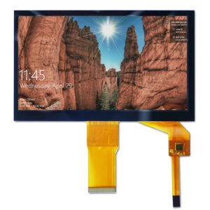
Projected capacitive touch, commonly called PCAP, detects a change in capacitance when a conductive object approaches the sensor. It commonly supports multi-touch and gesture input. The touch assembly may include a sensor, rigid cover lens, bonding adhesive, controller, flexible cable, and the TFT LCD module.
A current capacitive touch screen category includes PCAP products with USB or I²C connectivity and options involving cover-lens coatings and full lamination. These are category-level capabilities; the exact controller, interface, construction, and operating limits must be confirmed for each module.
Resistive touch uses two conductive layers separated by a small gap. Applied pressure brings the layers into contact, allowing the controller to calculate the touch coordinates. Four-wire and five-wire architectures are common. Standard resistive panels are normally used for single-point input.
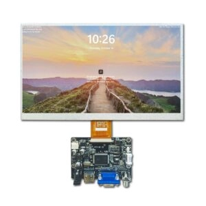
The resistive touch screen category includes touch-enabled TFT LCD modules in several sizes and interface configurations. Buyers should verify whether the touch controller is integrated, how calibration is handled, and which host-side connections are required.
Capacitive Versus Resistive Touch Screens: Quick Comparison
| Selection factor | Capacitive touch | Resistive touch | Procurement action |
| Input method | Conductive finger or compatible stylus | Finger, glove, or pressure stylus | Test the actual input method |
| Multi-touch | Commonly available | Normally single-touch | Define gesture and touch-point requirements |
| Thick gloves | May require tuning | Usually easier to activate | Supply glove material and thickness |
| Water exposure | Requires water-rejection validation | Pressure input may remain practical | Test droplets, condensation, and cleaning |
| Optical stack | Often uses a rigid glass cover lens | Usually includes a flexible top layer | Compare haze, reflections, and transmittance |
| Surface durability | Depends on glass and coating | Top layer can wear under repeated pressure | Define scratch and activation-cycle tests |
| Controller integration | Commonly USB or I²C | May use analog measurement or a controller | Confirm pinout, voltage, protocol, and drivers |
| User interface | Suitable for gestures and light touch | Suitable for deliberate point selection | Test accuracy and false activations |
The table is a screening tool rather than a final specification. Performance varies with the sensor, controller, firmware, bonding stack, grounding, enclosure, and environmental conditions.
Which Technology Is Better for Industrial Gloves?
Resistive touch is generally the simpler choice when operators use thick or electrically insulating gloves. Because activation depends on pressure, the panel does not require a conductive path through the glove. Stylus input is also practical when the application needs precise point selection.
Capacitive touch can support gloves when the sensor and controller are designed and tuned for that requirement. However, “glove compatible” is too broad for an acceptance criterion. Conductive gloves, disposable gloves, and thick work gloves produce different electrical conditions.
The purchasing specification should identify:
- Glove material and maximum thickness
- Required touch force
- Minimum target size
- Expected input speed
- Edge and corner accuracy
- Whether wet-glove operation is required
- Acceptable missed-touch and false-touch behavior
Samples should be tested with production gloves rather than bare-finger demonstrations.
How Do Moisture and Contamination Affect Touch Performance?
Water can alter the electrical field around a capacitive sensor. Controller algorithms may distinguish a finger from droplets, but performance depends on the electrode pattern, cover-lens thickness, firmware, grounding, and amount of liquid. A general water-resistance statement does not establish reliable wet-touch operation.
Resistive panels respond to pressure and may be less sensitive to the electrical properties of surface contamination. However, moisture can still enter an inadequately sealed assembly or collect around the bezel. Cleaning chemicals, oil, dust, and repeated wiping can also affect the top layer.
Engineering teams should define separate tests for:
- Stationary water droplets
- Condensation
- Wet-finger or wet-glove input
- Cleaning-agent exposure
- Oil or dust contamination
- Recovery after the surface is dried
- False touches during cleaning
Touch testing must include the final bezel, gasket, adhesive, and enclosure. A panel tested separately may behave differently after installation.
What Must Be Checked During LCD Module Integration?
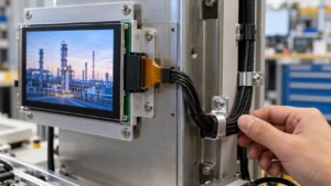
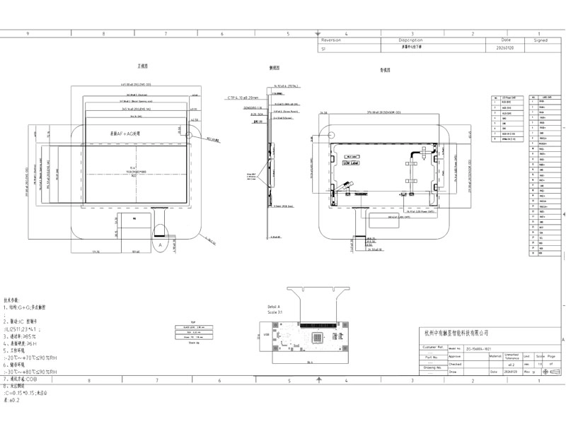
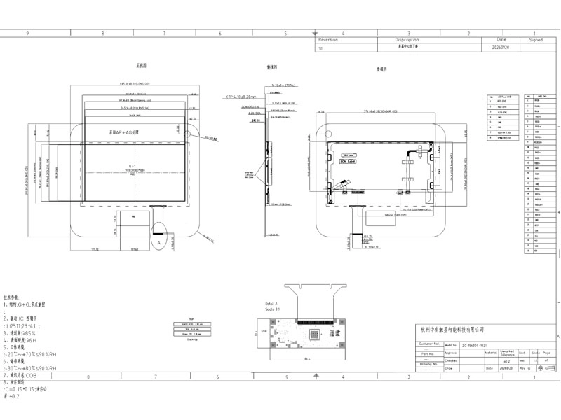
Touch technology cannot be selected independently from the TFT LCD module. Mechanical drawings should be reviewed for the module outline, active area, viewing area, touch-sensor outline, cover-lens dimensions, total thickness, cable exit, connector position, and mounting clearances.
Bezel pressure is particularly important for resistive touch because unintended pressure near the edges may affect operation. Capacitive assemblies require attention to grounding, nearby metal, electrical noise, and the distance between the sensor and surrounding components.
Electrical review should cover:
- Touch-controller part number
- Supply and logic voltage
- USB, I²C, SPI, or analog connections as applicable
- Connector model and pin assignment
- Interrupt and reset signals
- Cable length and routing
- Host driver and operating-system support
- Firmware revision and configuration ownership
- Grounding and electromagnetic-interference controls
The LCD interface and touch interface are separate specifications. A module may use one interface for image data and another for touch coordinates.
Optical Bonding, Cover Glass, and Surface Treatments
Capacitive assemblies often use a custom cover lens. Thickness, printed border, edge treatment, mounting holes, and surface coatings can affect both mechanical fit and touch sensitivity. Anti-glare, anti-reflective, anti-fingerprint, and antibacterial treatments should be specified by measurable requirements rather than coating abbreviations alone.
Optical bonding may reduce internal reflections and prevent an open air gap between the touch panel and LCD. It also changes the assembly process and repairability of the component stack. Procurement teams should request the bonding material, stack drawing, cosmetic criteria, and sample inspection method.
For resistive touch, the flexible top layer, spacer construction, and tail position require review. Buyers should compare visible haze, Newton rings, surface scratches, activation force, and calibration stability using an approved limit sample.
How Should Samples and Production Batches Be Validated?
A golden sample should be approved only after mechanical, electrical, optical, touch, and environmental checks. Testing should use the production processor board, power supply, enclosure, software, gloves, stylus, and cleaning materials.
Acceptance criteria can include:
- Coordinate accuracy across a defined grid
- Edge and corner response
- Activation force or sensitivity
- Multi-touch behavior where required
- Response after power cycling
- False-touch performance near electrical noise sources
- Operation at specified temperature limits
- Wet and contaminated surface behavior
- Cover-lens and cosmetic defect limits
- Cable, connector, and packaging inspection
Batch documentation should identify the LCD module, touch sensor, controller, firmware revision, cable drawing, and approved construction. Purchasing agreements should also address engineering-change notification and the process for validating substitute components.
What Supplier Evidence Should Buyers Request?
A supplier should provide revision-controlled drawings, interface documentation, controller information, operating conditions, optical specifications, and sample records relevant to the proposed module. Unsupported statements such as “industrial quality” or “waterproof touch” should be converted into defined test conditions and acceptance limits.
The current Miqidisplay website lists both touch technologies and describes customization involving touchscreen additions, cover glass, cable configuration, connectors, interfaces, PCB modifications, and bonding. These are website-stated capabilities, so exact applicability, tooling requirements, sample quantity, lead time, and commercial terms should be confirmed for each project.
FAQ
Is capacitive touch always more durable than resistive touch?
Not necessarily. A glass-covered capacitive panel may resist surface scratches better, while a resistive panel has a flexible working surface that can wear under repeated pressure. Durability must be evaluated against the specified impact, scratch, chemical, and activation-cycle conditions.
Can resistive touch support multi-touch?
Standard four-wire and five-wire resistive panels are normally used for single-point input. Projects requiring gestures or multiple simultaneous touch points should confirm the technology and controller before selection.
Can capacitive touch work through thick cover glass?
It may, but increasing glass thickness reduces the detectable signal. The sensor pattern and controller tuning must support the specified glass material, thickness, coatings, and printed border.
Which touch technology is less expensive?
Module price depends on size, construction, controller, cover lens, bonding, customization, tooling, and order quantity. Buyers should compare complete project cost, including integration, testing, rejected assemblies, and future changes.
What information is needed before requesting samples?
The sample brief should include LCD size, resolution, brightness, viewing direction, image interface, touch technology, touch interface, cover-lens drawing, glove or stylus requirements, operating conditions, enclosure details, software platform, quantity forecast, and destination market.
Conclusion: Selecting the Right Industrial Touch Module
Capacitive versus resistive touch screens for industrial LCD modules should be selected from documented operating requirements rather than general technology preferences. Capacitive touch is usually favored for multi-touch and glass-surface interaction, while resistive touch remains practical for pressure input, thick gloves, and stylus operation.
For a project-specific review, procurement teams can contact Miqidisplay with the LCD dimensions, resolution, interfaces, touch method, cover-glass drawing, operating environment, sample quantity, and forecast volume. Providing these inputs supports a focused compatibility review and sample plan.
Email: mary@miqidisplay.com
WhatsApp: +86 189 6801 5464; +44 07892800850