





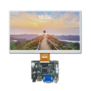
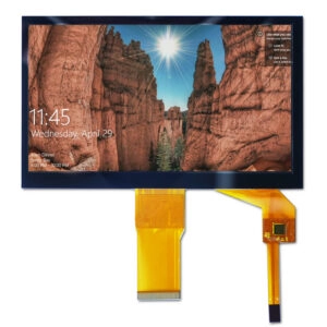




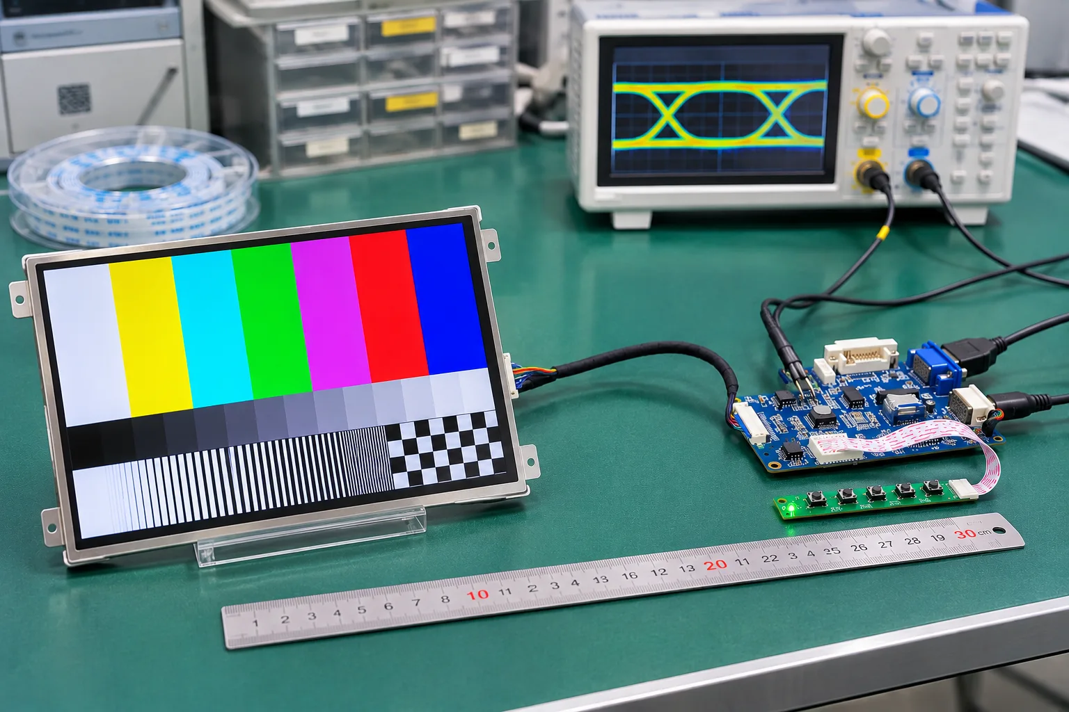
LCD cable length affects signal integrity by changing the loss, delay, and noise exposure between a driver board and its panel. For procurement, the acceptable length is the length demonstrated to meet the exact assembly’s electrical requirements under its intended operating conditions. A cable that produces a clear image on a bench has not necessarily established enough margin for production.
Before approving an extension, ask the supplier to identify the tested panel, driver board, cable construction, operating mode, and acceptance criteria. Those details turn a general statement about cable reach into evidence engineering and purchasing can evaluate.
Why There Is No Universal LCD Cable-Length Limit
The term “LCD cable” covers different interfaces and constructions. LVDS, parallel RGB, eDP, and MIPI connections have different electrical requirements. The permissible distance also depends on signaling rate, transmitter characteristics, receiver limits, connector transitions, and the cable itself.
An HDMI input on a driver board does not establish the reach of its downstream panel connection. Define which segment is being extended before discussing a maximum distance. Complete the panel and driver-board compatibility review first; this length assessment then determines whether the selected interconnect preserves adequate electrical margin.
A published distance for another assembly is useful background, but cannot approve the proposed configuration. Even a demonstrated LVDS cable length applies only to the conditions and components covered by that demonstration. Ask what changes would invalidate the stated limit.
What Additional Length Does to the Signal
Loss reduces amplitude and distorts transitions
Conductors and dielectric materials introduce losses that vary with frequency. Increasing length generally adds attenuation and can make received transitions less distinct. Different parts of the waveform are affected differently, allowing previous bits to influence the signal being sampled.
The resulting concern is receiver margin. A link may display an image while having little allowance for supply variation, temperature, or interference. Request measurements at the receiving end, using a method appropriate to the interface, rather than accepting a transmitter waveform as evidence of panel-side performance.
Reflections depend on the complete interconnect
Impedance changes at connectors, adapters, cable transitions, and termination can reflect energy back along the path. The timing of these reflections determines how they interact with later transitions. Length changes that timing, so adding an extension can alter performance even when its conductors appear equivalent.
Review the whole path, including board traces and intermediate connectors. Replacing one continuous cable with two sections and an adapter introduces additional transitions. Approval for the original cable therefore cannot automatically cover the extended assembly.
Skew consumes the timing allowance
Differential pairs require control of propagation differences between their conductors. A display link with a forwarded clock may also depend on the timing relationship between clock and data pairs. Unequal delay consumes the available sampling allowance.
Equal physical length does not necessarily mean equal propagation delay across different constructions. Ask engineering to distinguish intra-pair skew from inter-pair skew and identify the applicable limits. Cable delay should be assessed together with the relevant board routing and component timing requirements.
Why Equal-Length Cables Can Perform Differently
Two cables can share the same overall length, connector, and pin count while presenting different electrical channels. Conductor dimensions, insulation, pair geometry, shielding, and manufacturing tolerances can change loss, impedance, balance, and propagation delay.
For an LVDS cable specification, request the electrical properties needed by the actual interface. These may include differential impedance, insertion loss over the relevant frequency range, and skew. The supplier should identify whether a value is measured, guaranteed within a defined tolerance, or merely typical.
FFC and FPC describe interconnect constructions rather than a guaranteed transmission capability. A longer version with matching pitch may still require electrical evaluation. Shielding can help with certain interference paths, but does not independently establish acceptable attenuation or timing.
Compare the Proposed Length With a Controlled Reference
Start with an assembly whose performance and configuration are documented. Keep the panel, board revision, firmware, output settings, and test method consistent while comparing the reference cable with the proposed longer cable.
If construction or connectors must also change, record those differences explicitly. The result then validates a new interconnect configuration, rather than isolating length alone. This distinction matters when purchasing later considers another cable source.
A useful comparison should cover:
- The reference length and the longest proposed production length.
- Required resolution, refresh rate, and supported operating modes.
- Suitable patterns that exercise transitions and link activity.
- Specified supply and temperature conditions.
- The intended installed cable route and relevant interference exposure.
- Receiver-side electrical results and observed image behavior.
Agree the acceptance limits before testing. Use the transmitter, receiver, and panel requirements to select meaningful measurements; do not invent one generic eye-opening threshold for every interface.
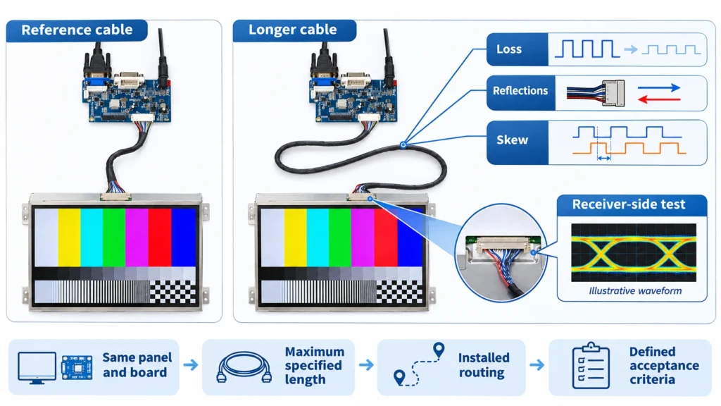
For parallel RGB, voltage levels and setup-and-hold timing may be central. For a serial differential link, channel loss, jitter, skew, or an applicable eye assessment may be relevant. Test access and probing should be reviewed so the measurement itself does not materially disturb the connection.
What a Supplier’s Cable-Length Report Must Establish
A report should let another engineer understand exactly what passed and under which conditions. A statement such as “long cable supported” leaves too much undefined for sample approval.
| Required record | What it establishes |
| Panel and driver-board identification | Which endpoints the result covers |
| Cable drawing, length datums, and tolerance | Which physical assembly was evaluated |
| Interface settings and operating mode | Which signaling conditions were exercised |
| Installed route, supply, and temperature | Which application conditions were represented |
| Instruments, probe points, and methods | How the electrical evidence was obtained |
| Acceptance limits and measured results | Why the configuration was accepted |
| Sample quantity and test duration | The scope and limitations of the demonstration |
Separate demonstrated conditions from untested assumptions. A room-temperature result does not establish performance throughout the required temperature range. One tested cable also does not establish the variability of all production cables.
If power shares the harness, request a separate voltage-drop assessment at the module. A signal-quality report does not establish adequate power delivery.
Use the Evidence to Approve the Sourcing Decision
Miqidisplay offers LCD modules with driver boards, providing a relevant starting point for a coordinated component inquiry. Confirm whether available evidence covers the requested cable length or only the supplied configuration.
For a 10.1-inch LCD module with an LVDS driver connection, diagonal size does not determine cable reach. Identify the exact module and board, then request assessment of the proposed harness and operating conditions.
Approve the cable only when the evidence covers the purchasing requirement. If it does not, identify the missing test or review board placement and interconnect architecture with engineering. Retain the validated electrical construction and length tolerance in the purchase specification.
Conclusion
A defensible LCD cable-length limit comes from the complete channel and its test conditions. Compare the proposed interconnect with a controlled reference, assess receiver margin, and require a report that states what was tested. This gives procurement a concrete basis for approving an extension.
FAQs
What is the maximum LVDS cable length for an LCD?
There is no universal value. Use a validated limit for the exact transmitter, panel, cable, operating mode, and application conditions.
Does a clear image prove an extended cable is acceptable?
It demonstrates operation under the observed conditions. It does not quantify electrical margin or cover untested conditions.
Can matching connectors justify a cable substitution?
No. Confirm pin assignments and the electrical properties of the replacement, then determine whether existing validation still applies.
Should the longest production cable be tested?
Yes. Include its permitted tolerance and intended route, while checking other conditions that could represent the electrical worst case.
Request a Miqidisplay Cable-Length Fit Review
Request a Miqidisplay technical fit review with the display type, size, outline dimensions, active area, resolution, interface, touch requirement, brightness, viewing direction, operating temperature, quantity, and drawings. Include driver-board details, cable length and tolerance, mechanical constraints, and integration environment. These inputs support assessment of component fit and discussion of customization scope, sample evidence, documentation, and batch consistency.