





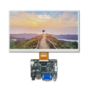
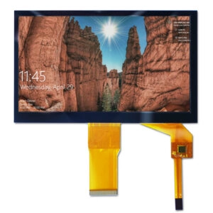
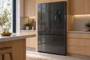
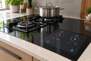

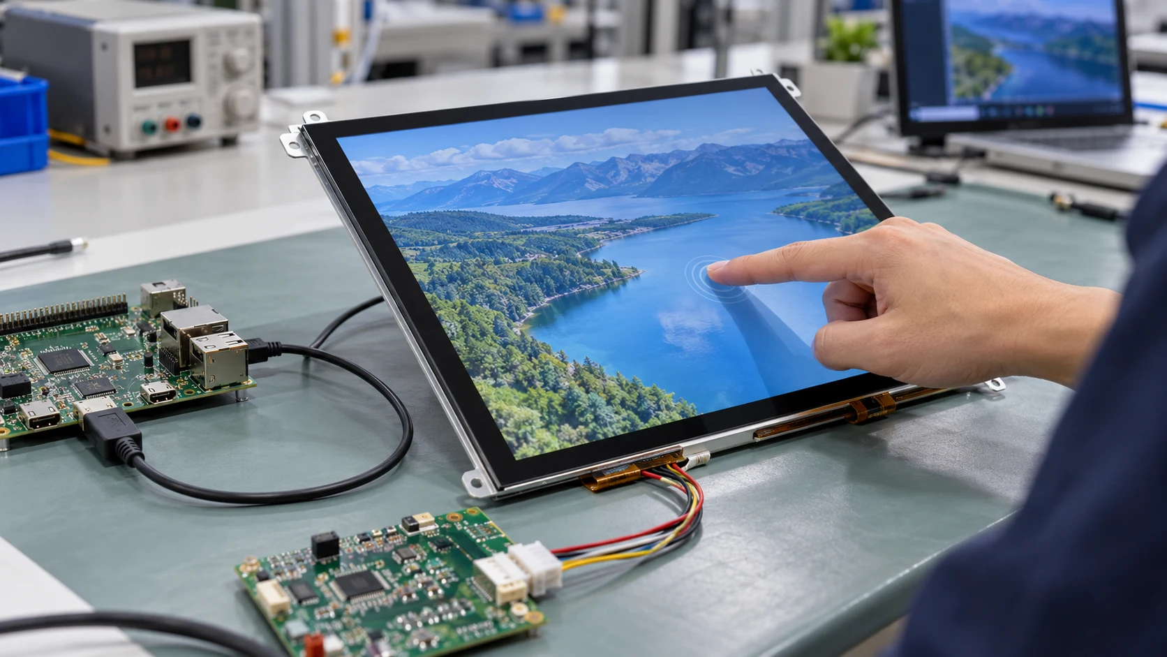
For an OEM capacitive touch panel, USB and I2C are not interchangeable cable choices. They determine how the touch controller communicates with the host board, which affects wiring, firmware, enclosure design, driver support, validation work, and long-term sourcing risk.
The practical choice depends on the host processor, software architecture, cable path, power design, operating environment, and production goals. USB is often convenient when the host already supports standard peripheral devices. I2C can be more suitable when the touch panel is integrated directly into an embedded controller with limited pins and tightly managed firmware.
What USB and I2C Mean in a Touch Panel Design
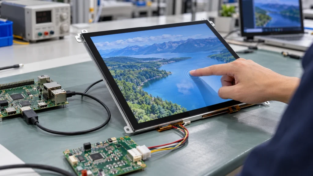
USB is a host-peripheral interface. The touch controller typically appears to the host as a standard input device or another defined USB peripheral. This can simplify initial integration when the operating system, processor board, and driver stack already support the required USB class.
I2C, also written as IIC, is a two-wire serial bus using SDA and SCL, together with power and ground. The host controller communicates directly with the touch controller through firmware. This can reduce signal count and support compact embedded designs, but the engineering team must confirm addressing, voltage levels, timing, initialization commands, and software compatibility.
The interface belongs to the touch function, not necessarily the LCD image interface. A module may use one interface for display data and another for touch data. Therefore, an OEM specification should record the LCD interface and touch interface separately.
The Main Selection Criteria
1. Host processor and software support
Start with the host board, not the touch panel. Identify the processor or system-on-module, available ports, supported voltage domains, operating system, and existing touch software.
USB may reduce software effort when the host already supports the required USB touch device behavior. However, the project should still verify enumeration, suspend and resume behavior, power-up timing, and any required vendor configuration.
I2C requires a compatible controller peripheral and firmware driver. The team should confirm the bus speed, address assignment, interrupt method, reset behavior, and initialization sequence. If the processor lacks a suitable I2C channel or the software team cannot support the controller protocol, I2C may create more integration work than expected.
2. Cable length and mechanical routing
I2C is commonly considered for short, controlled connections inside an embedded product. Its suitability depends on bus speed, pull-up design, capacitance, routing, noise, and cable construction. A longer cable or a noisy enclosure may require additional validation.
USB offers a familiar connector and broader peripheral cabling options, but the complete cable assembly still needs review. Connector height, bend radius, shielding, strain relief, and cable exit position can affect the mechanical design.
For either interface, request the actual connector drawing and pinout for the selected touch configuration. Do not approve a panel based only on the interface name.
3. Power architecture
The touch controller’s logic voltage and current requirements must match the host design. USB may provide a convenient power path in some architectures, but the available supply, startup behavior, protection, and grounding still need confirmation.
I2C generally separates communication from power delivery, so the host must provide the correct voltage rail and pull-up arrangement. A mismatch between the host voltage domain and the controller input level can require a translator or a different configuration.
The RFQ should identify the available host voltage, acceptable current range, power sequencing requirements, and whether the touch controller shares a supply with the LCD module.
4. Firmware ownership and update strategy
USB can be attractive when the host software team wants a standardized peripheral path. It may also support easier replacement during early prototype work if the host platform recognizes the device consistently.
I2C provides closer control over the touch controller and can fit products with a dedicated firmware architecture. That control also creates responsibility. The OEM team may need to manage register configuration, calibration data, interrupt handling, fault recovery, and firmware updates.
Before sample approval, define who owns the initialization file, configuration parameters, calibration procedure, and change control. A supplier quotation should not leave these responsibilities implicit.
5. Electromagnetic and environmental conditions
Capacitive touch performance can be influenced by noise, grounding, display stack construction, cable routing, cover-lens design, and enclosure materials. USB and I2C should therefore be evaluated as part of the complete touch assembly rather than as isolated communication standards.
For equipment exposed to gloves, moisture, vibration, or electrical noise, define the intended operating conditions before selecting the interface. Miqidisplay’s capacitive touch-screen category identifies configurable USB/IIC connectivity and options such as cover-lens treatments and touch configurations. The exact suitability still depends on the selected size, controller, host system, and environmental requirements.
USB vs. I2C: A Practical OEM Comparison
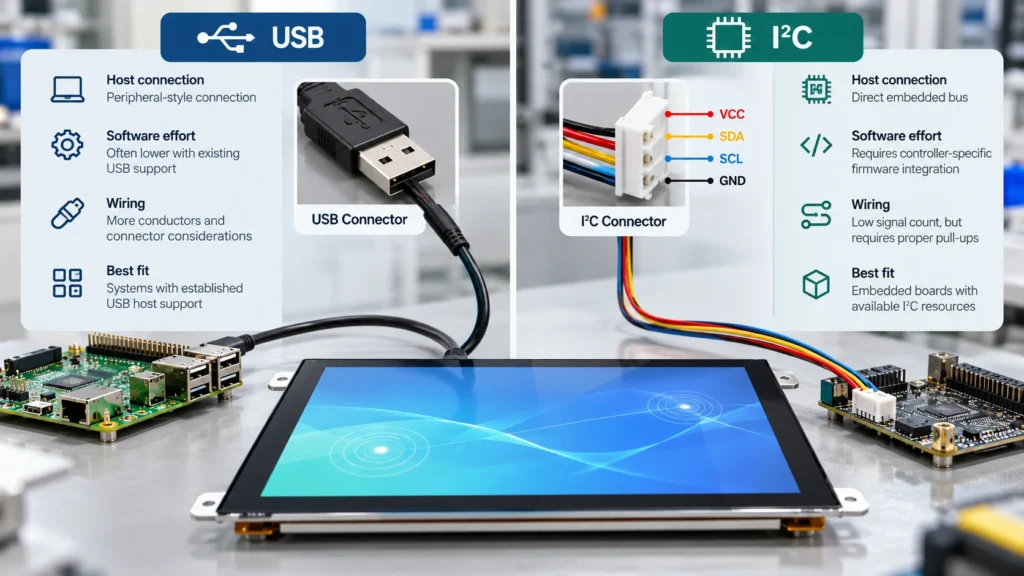
| Decision factor | USB | I2C |
| Host connection | Peripheral-style connection | Direct embedded bus |
| Software effort | May be lower with existing USB support | Requires controller-specific firmware integration |
| Wiring | More conductors and connector considerations | Low signal count, but requires proper pull-ups |
| Best fit | Systems with established USB host support | Embedded boards with available I2C resources |
| Cable planning | Familiar, but length and shielding require review | Usually favors controlled routing and validated capacitance |
| Design flexibility | Convenient for modular prototypes | Efficient for integrated production designs |
| Main risk | Driver, enumeration, and connector assumptions | Timing, voltage, address, and firmware assumptions |
This table is a starting point, not a substitute for interface validation. The correct choice is the one that fits the complete host and module architecture with the lowest unmanaged risk.
Product Configuration Must Match the Interface Decision
When comparing touch panels, keep the communication interface tied to the exact product configuration. A 10.4-inch capacitive panel may use IIC, while a 13.3-inch configuration may use USB. Similar diagonal sizes do not guarantee identical controllers, pinouts, cable exits, or firmware behavior.
For example, Miqidisplay lists an 11.6-inch industrial touch screen with IIC and a 17.3-inch capacitive touch panel with USB. These products demonstrate why interface selection should be made against a specific module rather than a general category assumption.
If the host board is optimized for a compact embedded bus, an IIC capacitive multi-touch panel may be a relevant starting point. If the architecture is built around a USB peripheral path, a USB capacitive touch panel may be easier to evaluate. In both cases, confirm the current datasheet, pinout, controller details, and mechanical drawing before release.
What to Include in an OEM RFQ
A useful RFQ should allow the supplier to assess both interface compatibility and mechanical fit. Include:
- Touch technology and required touch points
- Diagonal size, outline dimensions, and active area
- LCD interface and touch interface
- Host processor or controller information
- Logic voltage and available power rails
- Connector type, position, and cable length
- Resolution, viewing direction, and brightness target
- Operating temperature and environmental conditions
- Cover-lens thickness, surface treatment, and mounting method
- Quantity, prototype stage, drawings, and approval schedule
Ask the supplier to identify which values are confirmed, conditional, or still under review. Request interface timing information, initialization requirements, cable drawings, and any configuration files needed for sample validation.
Prototype and Production Checks
During sample evaluation, test the touch panel with the intended host board rather than a substitute platform alone. Verify startup, touch-coordinate accuracy, multi-touch behavior where required, suspend and resume, cable movement, and operation under the expected enclosure conditions.
Record the exact module revision, controller configuration, connector, cable, firmware, and mechanical stack used during testing. If USB and I2C versions are both being considered, compare them using the same test plan. Otherwise, differences in firmware or mechanical assembly can be mistaken for interface performance.
Before production release, confirm that the approved interface, pinout, cable, touch controller, and configuration data are frozen together. Any later substitution should trigger a compatibility review.
Conclusion
USB is often practical when the host already supports standardized peripheral integration and quick deployment is important. I2C can be a strong fit for embedded products that prioritize low signal count, direct controller access, and a tightly managed firmware architecture.
The decision should be based on host capability, software ownership, cable routing, power design, environmental conditions, and supplier documentation. Treat the touch interface as part of the complete LCD module specification, not as a late-stage accessory choice.
FAQs
Is USB always easier to integrate than I2C?
No. USB may simplify integration when the host software already supports the required device behavior. I2C may be more efficient when the product has a suitable embedded bus and an established firmware team.
Can the LCD and touch panel use different interfaces?
Yes. The LCD image interface and touch-controller interface can be different. Both must be documented and checked against the host architecture.
What is the most important item to verify before ordering samples?
Verify the exact touch controller interface, pinout, voltage requirements, connector, and initialization method for the selected module configuration.
Is I2C suitable for every cable length?
No. Suitability depends on bus speed, pull-up values, cable capacitance, routing, noise, and the controller configuration. The actual assembly should be tested.
When should the supplier join the interface decision?
Involve the supplier before the host board, connector location, and enclosure are frozen. Early review can expose compatibility or documentation gaps while design changes are still manageable.
Request a Miqidisplay Technical Fit Review
For an OEM sourcing assessment, contact the Miqidisplay technical team with the display type, diagonal size, outline dimensions, active area, resolution, interface, touch requirement, brightness, viewing direction, operating temperature, mechanical constraints, quantity, drawings, and integration environment. These inputs allow Miqidisplay to assess component compatibility, customization scope, documentation needs, sample requirements, and batch-consistency considerations before a sourcing decision is finalized.
Email: mary@miqidisplay.com
WhatsApp: +86 189 6801 5464