





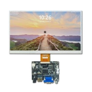
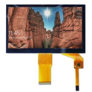


An LCD module interface should never be treated as a detail to “confirm later.” It affects the host processor, electrical design, firmware, cable routing, mechanical packaging, power architecture, test fixtures, and procurement options. If the interface is assumed rather than documented, a project can reach prototype assembly before discovering that the selected module cannot communicate with the intended system.
The practical solution is to create an interface assumptions record before engineering begins. This record does not need to contain every final specification. It needs to make uncertainty visible, assign ownership for unresolved points, and define the evidence required before a module is released for design.

Why Interface Assumptions Need Their Own Document
A conventional product requirements document may state the screen size, resolution, brightness, and touch requirement. Those details are important, but they do not fully describe the connection between the LCD module and the host system.
An interface assumption can affect several teams at the same time. For example, selecting an LVDS module may influence the processor board, differential-pair routing, connector position, cable length, timing configuration, and electromagnetic design. Selecting a MIPI DSI module may create different requirements for lane count, software initialization, power sequencing, and processor support.
If these assumptions remain in email threads or informal meetings, each team may work from a different interpretation. A short, revision-controlled register creates one reference point for engineering, sourcing, and the display-module supplier.
Teams that need background on specification fields can use this TFT LCD module datasheet guide before creating the register.
Define the Scope of the Interface Record
Start by stating what the record covers and what it does not cover. The scope should normally include the electrical interface between the host board and the LCD module, related control signals, power inputs, timing assumptions, connector and cable requirements, and the evidence needed for approval.
It should also identify the product stage:
- Early concept
- Architecture review
- Prototype design
- Engineering validation
- Production release
An assumption that is acceptable during concept work may be insufficient for prototype release. Recording the project stage prevents preliminary information from being mistaken for a final commitment.
The document should include a unique identifier, revision number, owner, creation date, and approval status. Each row should have a clear state such as “assumed,” “under review,” “confirmed,” or “rejected.”
Separate Host-Side and Module-Side Assumptions
Interface discussions often fail because the host system and the LCD module are described as if they have the same responsibility. They do not.
Host-side assumptions may include:
- Processor or display controller family
- Available interface types
- Supported lane count or data width
- Voltage domains
- Clock and timing capability
- Reset and enable behavior
- Software initialization responsibility
- Available connector location
- Maximum cable length and routing limitations
Module-side assumptions may include:
- Interface type and signaling method
- Pin assignment
- Connector series and contact orientation
- Required input voltages
- Backlight power arrangement
- Initialization sequence
- Timing windows
- Touch or auxiliary interface
- Operating temperature range
- Mechanical location of the cable exit
Each assumption should identify which side owns the information. If the host team assumes a module can operate at a certain voltage, but the supplier has not confirmed it, that item should remain open rather than being copied into the design as fact.
Build an Interface Assumptions Register
A useful register converts vague statements into testable entries. A practical format includes the following fields:
| Field | Purpose |
| Assumption ID | Provides traceability across revisions |
| Interface item | Names the signal, power, timing, or mechanical topic |
| Current assumption | States the working position in plain language |
| Source | Identifies the drawing, datasheet, schematic, or discussion |
| Owner | Assigns responsibility for confirmation |
| Risk if wrong | Explains possible design impact |
| Required evidence | Defines what will close the item |
| Status | Shows whether the item is open or confirmed |
| Change impact | Records affected documents or assemblies |
For example, “The module uses a four-lane MIPI DSI connection” is incomplete by itself. The register should also state whether this is based on a supplier datasheet, a preliminary quotation, or an internal assumption. It should identify the processor owner, note the risk of selecting an incompatible panel, and specify that final confirmation requires the module datasheet and pinout drawing.
This structure is more useful than a general statement such as “interface to be confirmed.”
Distinguish Facts, Constraints, and Decisions
Three types of information should be separated.
A fact is supported by a current technical document or an approved drawing. Examples include a specified connector type, stated voltage range, or published pin assignment.
A constraint comes from the equipment design. Examples include a fixed board location, a maximum cable bend radius, a restricted enclosure depth, or an available processor interface.
A decision is the selected direction after reviewing facts and constraints. For example, the team may decide to use an LVDS module because the host board already supports that interface and the cable route is relatively long.
Confusing these categories creates unnecessary disputes. A supplier datasheet does not prove that the chosen connector fits the enclosure. Similarly, a host processor capability does not prove that every module using the same interface will share the same timing or initialization behavior.
Record Electrical Assumptions in Sufficient Detail
The register should address more than the interface name. At minimum, review:
- Signal type and data direction
- Number of lanes or data lines
- Logic-level requirements
- Input power rails
- Backlight supply and control
- Reset, enable, and standby signals
- Clock or timing relationship
- Frame-rate or refresh assumptions
- Initialization commands
- Connector pin numbering
- Cable length and routing conditions
Do not convert a typical value into an acceptance limit without agreement. A datasheet may show a typical current or timing value, while the project requires a guaranteed operating range. Those are different statements and should be labeled accordingly.
If a value depends on the selected size, interface configuration, touch option, or backlight arrangement, mark it as conditional until the exact module configuration is identified.
Link Every Assumption to Evidence
An assumption is not closed simply because several people agree with it. It is closed when the required evidence is available and reviewed.
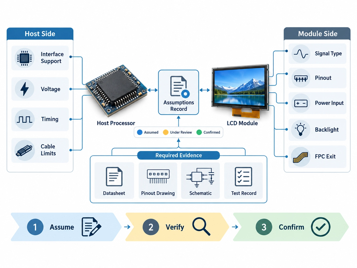
Useful evidence may include:
- Current LCD module datasheet
- Mechanical outline drawing
- Connector and pinout drawing
- Power-sequencing description
- Host processor reference design
- Interface initialization file
- Cable drawing
- Prototype test record
- Supplier clarification in a controlled project record
Use revision identifiers wherever possible. A link to a document without a revision can become ambiguous after a supplier updates the file.
For open issues, define the next verification action. “Check timing” is too vague. “Confirm the host controller supports the module’s lane count, pixel format, and timing range using the processor reference manual and supplier datasheet” is actionable.
Assign Responsibility and Change Rules
Each open assumption should have one accountable owner. Engineering may own processor compatibility, mechanical engineering may own connector location, procurement may own supplier-document status, and the display-module supplier may need to confirm module-specific parameters.
The record should also define what happens when an assumption changes. A revised pinout, connector, cable exit, voltage requirement, or timing range can affect several downstream documents. At minimum, the change review should consider:
- Schematic and PCB layout
- Cable drawing
- Firmware initialization
- Mechanical cutout
- Test fixture
- Bill of materials
- Supplier quotation
- Prototype schedule
A change log should record the previous assumption, the new information, the affected documents, and the approval decision. This is especially important when an alternative LCD module is proposed during sourcing.
Run a Pre-Engineering Interface Review
Before detailed engineering begins, hold a focused interface review using the assumptions register. The goal is not to discuss every display characteristic. The goal is to identify the assumptions most likely to cause redesign.
A useful review sequence is:
- Confirm the host processor and available interface options.
- Review the candidate LCD module’s electrical and connector information.
- Compare module requirements with host capabilities.
- Check mechanical cable exit and routing constraints.
- Identify unresolved power, timing, and initialization questions.
- Assign owners and due dates for open items.
- Define the evidence required for design release.
- Record the approved baseline and its revision.
The review should end with a clear decision: proceed with open risks documented, hold the design until specified items are confirmed, or evaluate another module configuration.
Prepare the Supplier Package
A supplier can respond more accurately when the assumptions record is included with the inquiry. Provide the intended application, host interface, processor information, required dimensions, resolution, active area, brightness target, viewing direction, temperature range, touch requirement, cable constraints, quantity, and project stage.
Mark which values are fixed, preferred, conditional, or still under evaluation. Include drawings when available, but identify whether they are preliminary or released.
Miqidisplay’s custom display solutions page identifies areas such as cable, connector, interface, and PCB customization. These possibilities still need to be assessed against the specific module, enclosure, host board, and project quantity. The assumptions record gives both sides a practical basis for that assessment.
How Miqidisplay Can Support the Review
Miqidisplay supplies TFT LCD display modules for OEM integration. A technical fit review can use the assumptions record to examine module compatibility, documentation gaps, interface configuration, cable requirements, and possible customization areas.
The review should remain conditional until the exact module, drawings, operating conditions, and project requirements are confirmed. A supplier should not be expected to resolve missing host-side information without a clear engineering package.
Conclusion
Documenting LCD module interface assumptions before engineering turns uncertainty into a controlled work item. The register should separate host and module responsibilities, distinguish facts from constraints, connect every assumption to evidence, and define how changes are reviewed.
This approach reduces late discovery of incompatible connectors, unsupported timing, incorrect power expectations, and unclear initialization responsibilities. It also gives engineering, procurement, and the display-module supplier a shared reference for evaluating alternatives without losing traceability.
FAQs
What is the most important interface assumption to document first?
Start with the host processor’s supported interface and the candidate module’s actual signaling method. Then verify lane count or data width, voltage levels, pinout, timing, and initialization requirements.
Should preliminary supplier information be treated as final?
No. Preliminary information should be labeled as an assumption or conditional value until it is supported by a current datasheet, drawing, approved clarification, or test evidence.
What evidence is needed before interface release?
The normal evidence package includes the module datasheet, pinout, mechanical drawing, power requirements, timing information, initialization details, cable definition, and confirmation that the host controller supports the selected configuration.
How should an alternative module be evaluated?
Compare the alternative against the complete assumptions register, not only size and resolution. Review interface compatibility, connector position, power, timing, mechanical fit, software impact, documentation status, and any required redesign.
When should the supplier be involved?
Involve the supplier before the host board and enclosure are frozen. Early review can identify documentation gaps and configuration risks while interface, cable, and mechanical decisions are still changeable.
Request a Miqidisplay Technical Fit Review
To request a Miqidisplay technical fit review, send the display type, diagonal size, outline dimensions, active area, resolution, interface, touch requirement, brightness, viewing direction, operating temperature, mechanical constraints, quantity, drawings, and integration environment to the Miqidisplay technical team. These inputs allow the team to assess component compatibility, customization scope, documentation needs, sample requirements, and batch-consistency considerations before a sourcing decision is finalized.
Email: mary@miqidisplay.com
WhatsApp: +86 189 6801 5464